PLC-5 and RSLogix 5
🌟 PLC-5 and RSLogix 5: Components, Modes, Download Operation, and Troubleshooting
PLC-5 is one of the classic Allen-Bradley control platforms, and even today, many plants still keep it in service because it combines a rugged hardware rack with dependable ladder-logic control for legacy production systems.
When engineers work on these systems, they usually need to understand four things clearly: the hardware structure, the RSLogix 5 software environment, the controller operating modes, and the correct way to handle program downloads without disturbing the running process.
A practical understanding of LEDs, alarms, and processor mode selection can save a lot of downtime, especially when a machine stops, and maintenance teams must decide whether the problem is in power, communication, I/O, or the application logic.
This article gives a simple field-oriented explanation so technicians, engineers, and maintenance staff can work more confidently with PLC-5 and RSLogix 5 systems.
⚙️ Major Components of PLC-5 and RSLogix 5
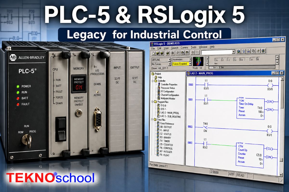
At the hardware level, a PLC-5 control system is built around a processor module installed in a 1771 chassis, along with a power supply and the required I/O modules.
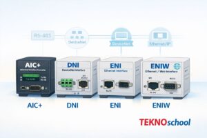
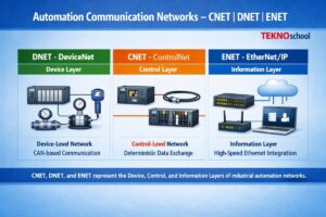
Depending on the processor model, the system may also provide onboard Universal Remote I/O, Extended Local I/O, or ControlNet communication, while DeviceNet support can be added with a 1771-SDN scanner module.
- Processor: The processor is the CPU of the PLC-5 system, and it executes the control program, manages memory, and handles communication with local or remote I/O.
- 1771 Chassis: The chassis provides the physical rack where the processor, I/O cards, and power supply are mounted together as one system.
- Power Supply: The power supply energizes the rack and is the first hardware item to check when the controller or modules appear dead.
- I/O Modules: Input and output modules interface the PLC with field devices such as pushbuttons, sensors, solenoids, valves, and motor starters.
- Battery: PLC-5 processors use a lithium battery to help retain the project during a power outage, so battery condition is important during maintenance planning.
On the software side, RSLogix 5 is the programming package used for PLC-5 controllers, and it supports projects created with Rockwell’s PLC-5 programming family.
The software is used to create or edit ladder logic, organize addresses and data tables, configure channels, document the program, and prepare the project for online monitoring or download to the processor.
- Ladder Editor: RSLogix 5 includes a free-form ladder editor that allows the programmer to write, verify, and modify control logic. [web:1]
- Data Tables: PLC-5 projects are organized around fixed data files, so understanding addresses and data-table structure is a basic part of working in RSLogix 5.
- Documentation Tools: The software also supports comments, reports, and printouts, which help technicians understand legacy programs faster.
- Communications Setup: A communication driver is needed so the engineering computer can establish a connection, go online, and transfer the program to the PLC-5 processor.
🔍 PLC-5 Mode of Operation
One of the most important things in PLC-5 is the key switch and processor mode, because mode selection decides whether the controller will run the machine, stop logic execution, or allow mode changes from software.
In RUN mode, the PLC executes the control program, but you cannot change the program structure through download or online edits; in PROGRAM mode, the controller does not execute the logic at all.
When the key switch is placed in REM, the processor can be controlled from the software, which means the engineer can change the mode from the workstation instead of touching the key switch on the panel.
This is the basic idea behind local versus remote operation in PLC-5 systems.
- RUN: The controller executes ladder logic and keeps the machine or process operating, but structural program changes are restricted.
- PROGRAM: The controller stops executing logic, which is useful for maintenance, full download work, and offline correction.
- REMOTE: The controller allows software-based mode control, which is necessary when you want to switch states from the programming computer.
In typical PLC-5 families, operating behavior may also be described as scanner, adapter, or local depending on processor type and system architecture.
Scanner mode lets certain PLC-5 processors scan and control local and remote I/O, adapter mode is used when a processor exchanges I/O quickly with a supervisory processor, and local mode means the processor scans only the I/O in its own chassis.
📥 PLC-5 Local and Remote Operation for Program Download
In day-to-day maintenance language, local operation usually means the technician is physically at the panel and uses the processor key switch directly, while remote operation means the key is in REM and mode changes are handled from the engineering software.
For downloading a program, this distinction matters because a processor locked in RUN cannot accept the same kind of structural change that is allowed when the controller is placed in an appropriate program-capable state.
A normal PLC-5 download workflow begins by establishing communications, going online with the controller, and confirming the processor mode before the file transfer is started.
In operational systems, uploading the current project first is a safer practice because downloading a new program can overwrite what is already stored in the controller.
- Step 1: Confirm the correct communication path and verify that the computer can connect to the PLC before any transfer action is attempted.
- Step 2: Check the key switch position, because REM allows mode changes from software, while hard RUN and hard PROGRAM are controlled locally at the processor.
- Step 3: Upload the existing application first if the machine is already running and you need to preserve the program currently in the controller.
- Step 4: Download only after verifying the correct file, because a fresh download can erase the previous software content in the processor.
- Step 5: After download, place the processor back into the required operating mode and confirm that the machine status is healthy before returning the equipment to service.
In short, local control is best when you want physical authority at the cabinet, and remote control is best when the panel key is set to REM and the software workstation must manage program mode changes.
For any live plant, always verify the active program, field condition, and process risk before initiating a download.
🚨 Troubleshooting Error LEDs and Alarms
LEDs are often the fastest first-level diagnostic tool on any PLC system because they immediately show whether the problem is related to power, controller fault, communication loss, or a defective I/O module.
Good troubleshooting starts with observing which LED is on, off, steady, or blinking, and then matching that behavior with the processor or module condition.
- Power issue: If the controller or rack appears dead, first inspect the incoming supply, rack power supply health, and module seating.
- Fault LED: A red or fault indication usually points toward a processor, program, or hardware error that must be diagnosed before normal operation can resume.
- Communication LED: Communication-related indicators help identify whether the PLC has lost its link to programming software, remote I/O, or networked devices.
- I/O module alarm: When a module in a slot shows a red blinking status, the fault is often localized to that module, its wiring, or the associated field device.
A practical troubleshooting routine is to identify the faulted slot, inspect the field wiring, confirm that the module is correctly plugged in, and then review the diagnostics in the software.
In demonstrated PLC diagnostic procedures, reconnecting or correcting the failed module condition can remove the slot fault indication, and the remaining error may then need to be reset or cleared in software.
Some alarms are not purely hardware alarms, because a processor may also stop or indicate an error if the loaded program, configuration, or communication state is inconsistent with the real chassis condition.
That is why good maintenance practice combines physical inspection, software diagnostics, and a final validation step after correction.
- Check 1: Verify supply power, rack health, and processor status first, because many apparent control failures start with a simple power problem.
- Check 2: Review the exact module slot that shows the red LED, and inspect its terminal wiring and field device condition.
- Check 3: Go online and read diagnostic or error information before replacing hardware blindly.
- Check 4: After correcting the issue, clear the fault and verify whether the controller needs to be re-downloaded or returned to the proper run state.
💡 Practical Field Tips
For old PLC-5 installations, the best maintenance habit is to keep a verified backup of the application, record the exact processor mode before intervention, and avoid unnecessary downloads on live equipment.
It is also wise to treat remote mode carefully, because software control is convenient but should only be used when the machine condition and safety status are fully understood.
If your team understands the hardware structure, the RSLogix 5 workspace, the operating modes, and the meaning of LEDs and alarms, PLC-5 troubleshooting becomes much faster and more systematic.
Even though PLC-5 is a legacy platform, disciplined mode handling and correct download practice still make the difference between a smooth restart and an avoidable shutdown.