Single Phase DC Motor Drives
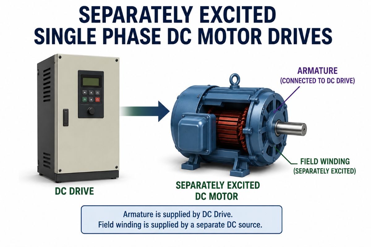
Separately Excited Single Phase DC Motor Drives
A separately excited DC motor has its armature and field circuits powered from independent sources, giving precise, independent control of speed and torque. Drive systems for these motors fall into two broad categories: AC-DC converter drives (used when the supply is AC) and DC-DC chopper drives (used when the supply is DC). Both achieve variable speed by adjusting armature voltage below base speed and by weakening the field current above base speed.
AC-DC Converter Drives: Semi-Converter and Full Converter
When a single-phase AC supply feeds a separately excited DC motor, thyristor-based controlled rectifiers — commonly called converters — are used to produce a variable DC output voltage. Two main configurations are the semi-converter and the full converter.
Single-Phase Semi-Converter Drive
A single-phase semi-converter (also called a half-controlled converter) uses two thyristors and two diodes in a bridge arrangement, plus a freewheeling diode. The freewheeling diode allows the load current to circulate freely during the negative half-cycle, preventing the output voltage from going negative. Because of this, the semi-converter operates only in one quadrant — positive voltage and positive current — making it suitable for applications where regeneration is not needed, such as fans, pumps, and small machine tools.
The key advantages are a better displacement power factor, lower RMS current, and reduced motor heating (approximately 44% less heating than a full converter). However, discontinuous conduction at light loads and low speeds results in poorer speed regulation than the full converter.
Single-Phase Full Converter Drive
A single-phase full converter uses four thyristors in a fully controlled bridge. Both positive and negative output voltages are possible, giving two-quadrant operation — positive or negative voltage with unidirectional current. This means the motor can operate in motoring mode (positive voltage) or regenerative braking mode (negative voltage, returning energy to the supply). The full converter is preferred where speed reversal or regeneration is required, such as in rolling mills, hoists, and printing presses. Adding a freewheeling diode to a full converter improves power factor while retaining most of the regenerative capability.
The field circuit of a separately excited motor is also commonly supplied through a separate single-phase semi-converter or full converter, allowing independent field control for speed regulation above base speed.
DC-DC Converter (Chopper) Drives
Where the supply is DC — from a battery bank, a diode rectifier fed from AC, or a DC bus — a DC-DC converter (chopper) converts a constant DC voltage into a variable DC voltage by rapidly switching a power device (IGBT, MOSFET, or GTO) on and off. Choppers operate at high frequency, giving lower armature current ripple, better dynamic response, and less motor heating compared to phase-controlled converters.
Single-Quadrant (One-Quadrant) Chopper Drive
Provides positive voltage and positive current only. The motor runs in one direction with no regeneration. Used for simple, low-cost applications like conveyor drives and small pumps.
Two-Quadrant Chopper Drive
Can provide positive voltage with both positive and negative current (or vice versa), enabling either motoring and regenerative braking in one direction, or forward and reverse motoring without regeneration. A typical two-quadrant chopper uses two switching devices and allows controlled energy recovery during braking.
Four-Quadrant Chopper Drive
Uses an H-bridge configuration with four switching devices and allows the motor to operate in all four quadrants — forward motoring, forward regeneration, reverse motoring, and reverse regeneration. This is the most versatile DC drive arrangement, used in servo systems, robotics, machine tools, and electric traction, where rapid and precise speed reversal is needed.
Speed Control Methods
Armature Voltage Control (Below Base Speed)
By varying the armature voltage while keeping the field current at its rated value, the motor speed is controlled proportionally below the base (rated) speed. This method maintains constant torque capability since the flux is constant. Both converters and choppers use armature voltage control as the primary speed regulation method for the lower speed range.
Field Current Control (Above Base Speed)
Above base speed, the armature voltage is held at its rated value, and the field current is reduced (field weakening), which reduces flux and increases speed. This gives constant power operation. Field current control is implemented through a separate field converter. The speed can be increased to two to three times the base speed this way, but at the cost of reduced torque capacity.
Protection of DC Motor Drives
Over-Voltage Protection
Sudden load rejection or converter malfunction can produce voltage spikes that damage the armature winding insulation. Over-voltage protection uses transient voltage suppressors, RC snubbers, or varistors across the armature terminals to clamp excessive voltages. Relay-based over-voltage detection circuits also trip the main contactor if the terminal voltage exceeds a set limit.
Over-Current Protection
DC motors are susceptible to high inrush or fault currents that can damage the commutator, brushes, and windings. Over-current protection is achieved through current-limiting in the firing circuit of the converter (limiting the firing angle when current exceeds a threshold), fast-acting fuses, and electronic current-limit loops in the controller. Thermal overload relays also protect against sustained overcurrent.
Field Failure Protection
Loss of field current is particularly dangerous: with no field flux, the back-EMF drops to near zero, causing the armature current to rise to destructive levels, and the motor may overspeed (runaway). A field failure relay — connected in series with the field circuit — monitors field current continuously. If the field current falls below a set threshold, the relay de-energizes the main contactor, disconnecting the armature supply immediately. In modern drives, a field current sensor and closed-loop field regulator detect and respond to field loss within milliseconds.
Converter Drive vs. Chopper Drive — Key Comparison
| Parameter | Converter (AC-DC) Drive | Chopper (DC-DC) Drive |
|---|---|---|
| Supply type | AC supply is directly used | DC supply required (battery or rectifier) |
| Output ripple | Higher ripple at low pulse numbers | Much lower ripple at high switching frequency |
| Speed regulation | Poorer at light loads (discontinuous conduction) | Better speed regulation, fewer discontinuous zones |
| Dynamic response | Slower (limited by supply frequency) | Fast response (high switching frequency) |
| Power factor | Poor at low speeds (lagging due to firing angle) | Power factor not applicable on DC side; unity on AC rectifier front-end |
| Harmonics | Significant current harmonics are injected into the AC line | Lower harmonics are easier to filter |
| Cost & complexity | Lower cost, simpler for direct AC supply | Higher cost; needs a DC source or an extra rectifier stage |
| Regeneration | Two-quadrant with full converter | Easy four-quadrant with H-bridge chopper |
| Typical applications | Rolling mills, hoists, and industrial drives | Servo drives, robotics, EVs, battery-powered traction |
In summary, converter drives are the natural choice when an AC supply is available and cost matters, while chopper drives excel where fast response, low ripple, and four-quadrant control are needed — particularly in servo and traction applications where the DC supply is already available or easily obtained from a front-end diode rectifier.