The Smoothing Reactor and the DC Line
The Smoothing Reactor and the DC Line: Transient Overvoltage, Protection, DC Breakers, and Monopolar Operation
The Smoothing Reactor and the DC Line-Between the converter valves and the overhead line that carries power across hundreds of kilometres sits a single large inductor: the smoothing reactor. It is one of the least glamorous components in an HVDC station and one of the most consequential. It shapes the direct current into something the line can carry cleanly, it limits how fast fault current can rise, and it forms the boundary across which every protection decision on the DC side is made. Understanding the smoothing reactor and the transmission line it feeds is the key to understanding how HVDC schemes stay stable during faults, how they recover afterward, and why they can keep delivering power on one pole when the other has failed.
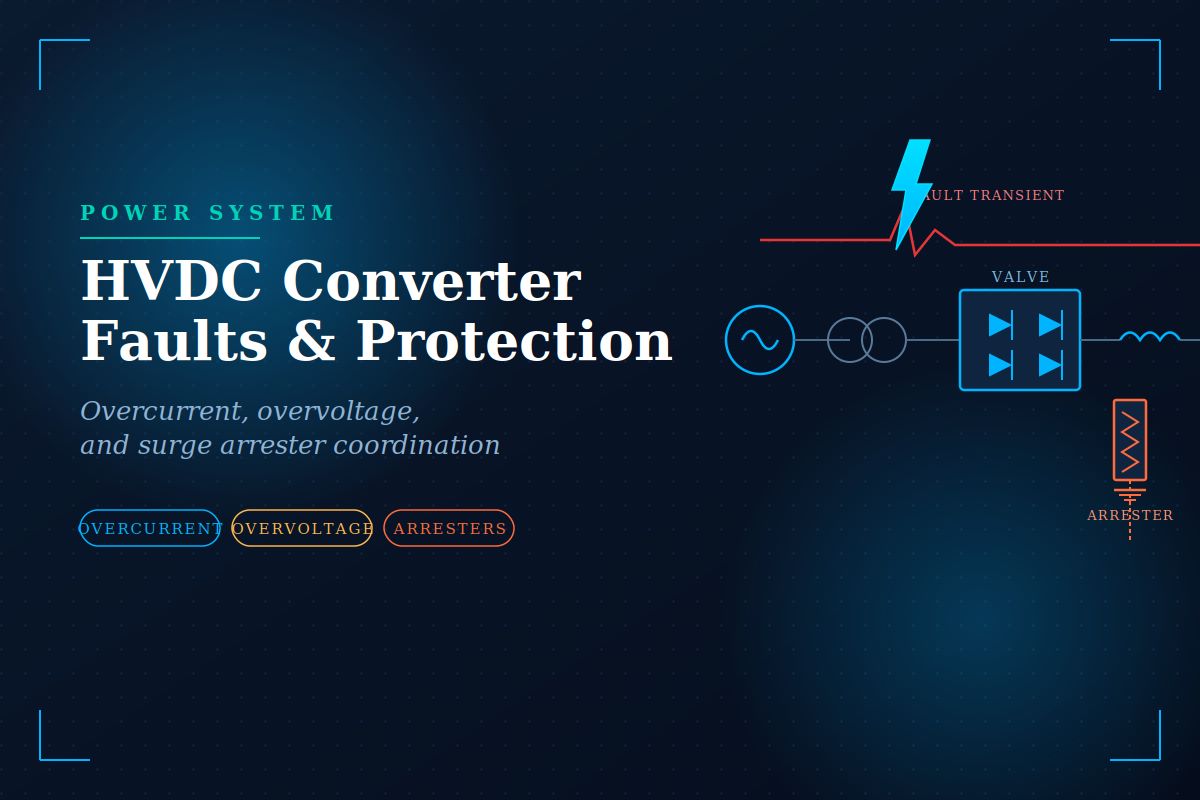
What the smoothing reactor does. A smoothing reactor is a large air-core or iron-core inductor, typically 100 to 300 mH, connected in series with each pole at the DC terminal of the converter. It performs three jobs simultaneously: it smooths the ripple in the direct current so the line carries a clean DC with minimal harmonic content, it limits the rate of rise of current during a DC fault so the valves survive until control action responds, and it prevents commutation failures at the inverter that would otherwise be triggered by fast current transients arriving from the line. A larger reactor gives better smoothing and current limiting but costs more, adds losses, and slows the control response — so its value is always a compromise.
The DC Line
An HVDC transmission line — whether an overhead line, a land cable, or a submarine cable — is electrically very different from its AC counterpart. It carries a constant voltage with no reactive power to manage, so there is no charging current to compensate and no stability limit set by the line’s electrical length. This is precisely why HVDC is chosen for long distances and for cable crossings where AC charging current would consume the entire capacity of the circuit. But the DC line stores energy in its own capacitance and inductance, and that stored energy becomes the dominant concern the moment a fault occurs. A line fault does not simply interrupt power flow; it releases the line’s stored charge into the fault and draws a rapid infeed from the converter, and the smoothing reactor is the only thing standing between that event and the valves.
Transient Overvoltage on the DC Line
Transient overvoltages on a DC line come from several sources. Lightning strikes on an overhead line inject steep-fronted surges that travel toward both terminals. Switching operations — energising the line, blocking the converter, or clearing a fault — launch travelling waves that reflect from the line ends and can reinforce at certain points. A fault on one pole of a bipolar line induces a transient on the healthy pole through the mutual coupling between the two conductors. And the sudden collapse of voltage at a fault point sends a rarefaction wave down the line whose reflection can produce a temporary overvoltage of significant magnitude.
These travelling waves are governed by the line’s surge impedance and propagate at close to the speed of light on overhead lines, somewhat slower in cables. When a wave reaches the smoothing reactor, the reactor’s inductance presents a high impedance to the steep front and reflects much of it, protecting the converter behind it. This is one reason the reactor is placed exactly where it is: it is not only a current limiter but a barrier that flattens the front of incoming surges so the valve arrester behind it sees a gentler, lower-energy transient. Insulation coordination on the DC line depends on this interaction between the travelling wave, the reactor, and the arresters at each terminal.
The reflection problem. A travelling wave doubles in magnitude when it reflects from an open circuit and inverts when it reflects from a short circuit. Because the smoothing reactor looks nearly like an open circuit to a fast transient, the voltage at the reactor terminal can momentarily approach twice the incoming surge magnitude. Arrester placement must account for this: the DC line arrester is positioned at the reactor terminal precisely because that is where the reflected wave produces the highest stress, not at the middle of the line where the travelling wave is still at its incident value.
Protection on the DC Line
DC line protection must distinguish a genuine line fault from a transient disturbance and must do so within a few milliseconds, because sustained fault current threatens the valves. The primary method is the travelling-wave or voltage-derivative protection: it monitors the rate of change of DC voltage and current at the line terminal. A line fault produces a characteristic signature — a steep collapse in voltage together with a rising current — that arrives as a wavefront and is unmistakable. The protection detects this front, confirms it against the current direction, and issues a trip command that forces the rectifier into force-retard, driving the DC voltage negative and extinguishing the fault current.
Because most overhead-line faults are transient — a lightning flashover clears itself once the arc is deionised — HVDC schemes use an automatic restart sequence. After force-retard extinguishes the fault current, the control holds the line de-energised for a de-ionisation interval of typically 100 to 300 milliseconds, then ramps the voltage back up. If the fault has cleared, full power is restored within a fraction of a second. If the fault persists, the sequence may retry at reduced voltage before the scheme blocks and alarms. This mirrors AC auto-reclosing but is achieved entirely through converter control, with no mechanical breaker operation on the line itself.
DC Breakers
In a two-terminal HVDC link, fault clearing is done by the converters themselves through force-retard, and no DC circuit breaker is needed on the line. But in a multi-terminal DC grid — where several converters connect to a common DC network — force-retard would shut down the entire grid to clear a single line fault. Here, a true DC circuit breaker becomes essential, able to isolate the faulted line while the rest of the grid keeps running.
Why is the DC breaker hard. An AC breaker clears the fault at a natural current zero that occurs every half-cycle. A DC current has no natural zero — it must be forced to zero. Modern hybrid DC breakers do this by commutating the current into a parallel branch of semiconductor switches and surge arresters that impose a counter-voltage, driving the current to zero within a few milliseconds and absorbing the enormous inductive energy released when a current of several kiloamperes is interrupted almost instantly. The engineering challenge is severe: the breaker must act in two to three milliseconds, far faster than any mechanical AC breaker, because the fault current in a low-impedance DC grid rises extremely quickly.
Monopolar Operation
A bipolar HVDC scheme has two poles — one at positive voltage, one at negative — sharing a common return path. Its great operational virtue is that if one pole is lost to a converter fault, a line fault, or planned maintenance, the scheme continues to deliver power through the surviving pole in what is called monopolar operation. The healthy pole typically carries its full rated current, so roughly half the total power keeps flowing rather than the whole link collapsing.
Return path options. During monopolar operation, the return current can flow either through a dedicated metallic return conductor or through the ground via electrodes at each station. Ground return avoids the cost of a return conductor and has very low resistance, but the continuous flow of direct current through the earth can cause corrosion of nearby buried metal structures and pipelines, and can bias the operation of transformers whose neutrals are earthed nearby. Many schemes therefore prefer metallic return for extended monopolar operation, using ground return only for short emergency periods. Some jurisdictions restrict ground return entirely for environmental reasons.
Effects of Proximity of HVDC Lines
When an HVDC line runs close to other infrastructure, several interaction effects must be managed. A DC line carrying ground-return current establishes an earth potential gradient around its electrodes that can induce currents in parallel pipelines, railway tracks, and communication cables, accelerating corrosion and creating touch-potential hazards near the electrode sites. Where an HVDC line runs in parallel with an AC line on a shared corridor, the DC field can bias the AC line’s transformers into partial saturation, and conversely, the AC line can induce ripple on the DC conductors through electromagnetic coupling.
The static electric field beneath an HVDC overhead line, together with the ions generated by corona at the conductors, produces a ground-level ion current and field that is regulated for public exposure. Where two HVDC lines share a corridor, or where an HVDC line parallels an AC line, corridor spacing and conductor arrangement are engineered to keep these coupled fields, induced voltages, and ion densities within limits. Electrode siting is chosen deliberately far from pipelines and dense buried metalwork, and cathodic-protection systems on nearby pipelines are coordinated with the HVDC operator. Proximity, in short, turns what looks like a single transmission line into a system that must be designed in the context of everything around it.