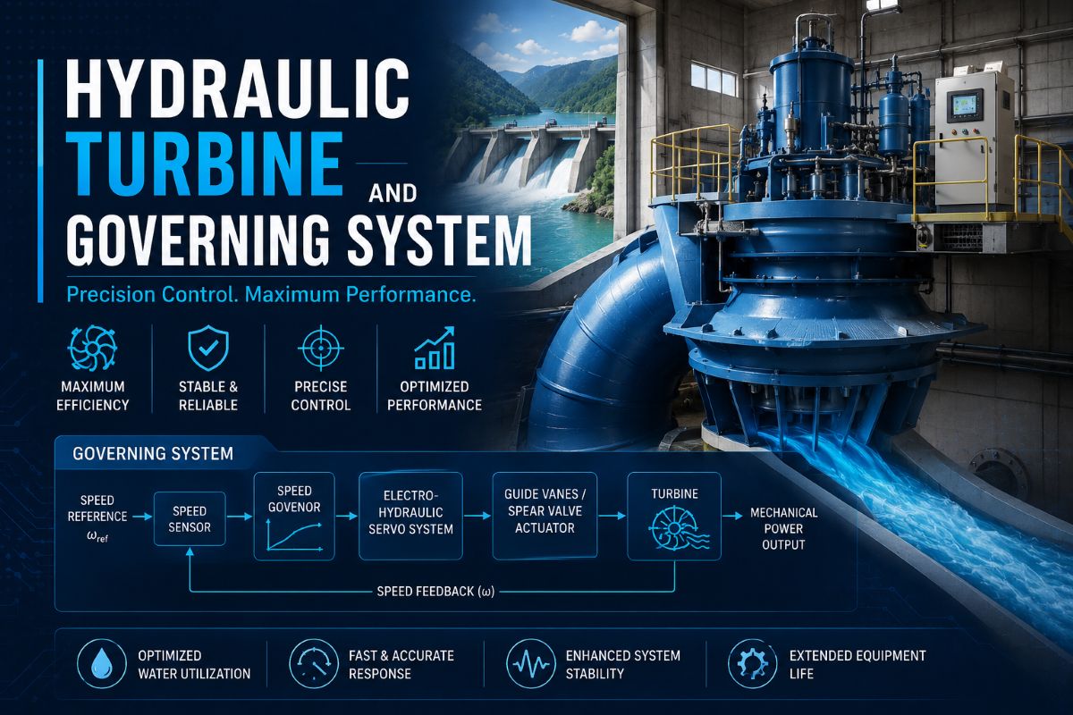
Hydraulic Turbine and Governing System
Hydraulic Turbine and Governing System
Hydraulic Turbine and Governing System, Non-Linear Turbine Model, Inelastic Water Column, Governors and Detailed Hydraulic System Model
Hydraulic turbines convert the potential and kinetic energy of water into mechanical torque that drives synchronous generators. Unlike steam or gas turbines, where the working fluid is compressible, the water flowing through a hydraulic turbine is essentially incompressible, and the dynamics of the water column in the penstock introduce unique characteristics — most notably the phenomenon of water hammer and the non-minimum phase response that complicates governor design. Accurate modelling of the hydraulic turbine and its governing system is essential for power system stability studies, load-frequency control analysis, and islanding simulations.
Fundamental Concept of Hydraulic Turbine Operation
A hydraulic turbine operates by directing water from a reservoir through a penstock (a large pipe or tunnel) onto the turbine runner. The power output depends on two primary variables: the water flow rate through the turbine and the effective head (the height difference between the reservoir level and the turbine outlet, minus hydraulic losses). A gate mechanism — wicket gates for Francis and Kaplan turbines, or a needle valve (spear) for Pelton turbines — controls the flow of water and thereby regulates the mechanical power delivered to the generator shaft.
The critical characteristic that distinguishes hydraulic turbines from thermal prime movers is the water inertia effect. When the gate opening is suddenly increased to admit more water, the turbine power does not increase immediately. Instead, there is an initial transient drop in power because the water in the penstock cannot accelerate instantaneously — the increased gate opening momentarily reduces the pressure head at the turbine before the water flow has time to increase. This initial inverse response is a defining feature of hydraulic turbine dynamics and is the primary reason why hydraulic turbine governors require a transient droop or dashpot compensation.
Non-Linear Turbine Model: Assuming Inelastic Water Column
The simplest yet physically meaningful model of a hydraulic turbine assumes an inelastic (incompressible) water column — meaning that pressure waves travel at infinite speed through the penstock and the water behaves as a rigid, incompressible mass. This assumption is reasonable when the penstock is short relative to the wavelength of the disturbance, or when the study time frame is long compared to the water hammer wave travel time.
Under this assumption, the fundamental dynamic equation governing the water flow in the penstock is derived from Newton’s second law applied to the water column. The rate of change of water flow is proportional to the net head acting on the water mass and inversely proportional to the water starting time constant, TW. The water starting time, TW, is a key parameter representing the time required for the water in the penstock to accelerate from rest to rated flow under the action of the rated head. It is defined as TW = LQ0 / (AgnH0), where L is the penstock length, A is the cross-sectional area, Q0 is the rated flow, H0 is the rated head, and gn is gravitational acceleration. Typical values of TW range from 0.5 to 5.0 seconds.
The non-linear aspect of the model arises from the relationship between flow, gate opening, and head. The turbine flow is proportional to the gate opening multiplied by the square root of the head across the turbine. The turbine mechanical power is proportional to the product of flow and head. These relationships are inherently non-linear because the head itself depends on flow — as the flow increases, the velocity head consumed in the penstock reduces the effective head at the turbine. Additionally, the relationship between gate position and actual flow is non-linear due to the square root dependency.
This non-linear inelastic model captures the essential inverse response behaviour: when the gate is opened, the flow initially remains nearly constant (due to water inertia), so the head at the turbine drops. The power output actually decreases momentarily before the water column accelerates and the flow increases to deliver higher power. The duration of this initial power dip is directly related to TW.
Governors for Hydraulic Turbines
The governor controls the gate position to regulate turbine speed (or power output) in response to frequency deviations. Due to the non-minimum phase response of the water column, a simple proportional governor that works well for steam turbines would cause instability on a hydraulic turbine. If the governor responds too aggressively to a frequency drop by rapidly opening the gates, the initial power dip (due to water inertia) worsens the frequency deviation, causing the governor to open the gates even further — leading to sustained oscillations or instability.
Mechanical-Hydraulic Governors: Traditional governors for hydraulic turbines use a dashpot mechanism to provide transient droop compensation. The transient droop (RT) is significantly higher than the permanent or steady-state droop (RP). When a frequency disturbance occurs, the governor initially responds with a high droop (slow response), allowing the water column time to accelerate. As the dashpot slowly resets through its orifice, the effective droop reduces to the permanent value, and the gate moves to its final position. The dashpot reset time (TR) is typically set to approximately 5 × TW to ensure stable operation, and the transient droop RT is typically 2 to 3 times the permanent droop RP.
Electro-Hydraulic and Digital Governors: Modern governors use electronic or digital controllers that implement PID control with tailored gain scheduling. The proportional-integral-derivative structure is tuned to account for the water starting time, with the derivative action providing the equivalent of transient droop compensation. Digital governors offer advantages including precise tuning, nonlinear gain scheduling based on gate position, automatic adaptation to varying head conditions, and the ability to implement multiple control modes such as power control, level control, and frequency control with smooth mode transitions.
Detailed Hydraulic System Model
While the inelastic water column model is adequate for many stability studies, a detailed hydraulic system model is required when penstock lengths are significant or when an accurate representation of water hammer effects is necessary. The detailed model treats the water column as an elastic medium where pressure waves propagate at a finite speed determined by the bulk modulus of water and the elasticity of the penstock walls. The wave travel time Te = L/a, where a is the pressure wave velocity (typically 900–1200 m/s in steel penstocks), becomes a critical parameter.
In the elastic model, the penstock is represented using the travelling wave equations (also known as the method of characteristics or the d’Alembert solution). The head and flow at the turbine end are expressed in terms of the head and flow at the reservoir end, with a time delay equal to the wave travel time. This results in a transfer function with a hyperbolic tangent term that captures the multiple reflections of pressure waves between the reservoir and the turbine. For a simple conduit with a constant cross-section and an ideal reservoir (constant head), the transfer function relating head change to flow change involves the term Z0 × tanh(Tes), where Z0 is the hydraulic surge impedance.
For complex hydraulic layouts — involving surge tanks, multiple penstocks, branching conduits, or tunnels of varying cross-section — the detailed model becomes a multi-segment representation. Each segment is characterised by its own wave travel time and surge impedance. Surge tanks, which are open reservoirs connected to the penstock to absorb pressure transients, introduce additional dynamics with their own natural oscillation period. The surge tank level oscillations can have periods of several minutes and must be accounted for in long-term dynamic studies and governor tuning.
The detailed model also accounts for hydraulic losses in the penstock (friction head losses proportional to the square of flow velocity), turbine efficiency variations with operating point, and the effects of speed deviation on turbine flow characteristics. For pumped-storage plants operating in both generation and pumping modes, the model must capture the entirely different dynamic characteristics in each mode, including the four-quadrant operating region of the pump-turbine.
Key Takeaway
Hydraulic turbine modelling centres on the unique inertia of the water column — the initial inverse power response that demands specialised governor designs with transient droop or equivalent PID compensation. The choice between the simpler non-linear inelastic model and the detailed elastic travelling-wave model depends on penstock length, study objectives, and whether water hammer dynamics are relevant. Properly tuned governors, whether mechanical-hydraulic or modern digital, must respect the water starting time TW to achieve stable, well-damped frequency regulation.