
Power System stability
Improving Power System Stability
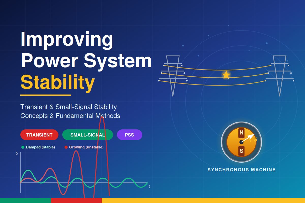
A power system is judged not only by how reliably it delivers energy under normal conditions, but by how gracefully it recovers from disturbances. Faults, line outages, sudden load changes, and generator trips all push the system away from equilibrium. Stability improvement is the engineering effort to ensure the system stays synchronised after large disturbances and remains well-damped under small ones. Two distinct categories — transient stability and small-signal stability — demand different countermeasures, although several modern devices serve both purposes.
Transient stability concerns the ability of synchronous machines to remain in step after a large disturbance such as a three-phase fault. Small-signal stability concerns the damping of small oscillations that continuously arise around the operating point — local plant modes, intra-plant modes, and inter-area modes.
The Underlying Physics
Every method of stability improvement can be traced to one principle: the swing equation governs rotor dynamics, and the power–angle relationship Pe = (E·V/X)·sinδ governs how much electrical power a generator can deliver as a function of its rotor angle. Anything that increases transferable power, reduces the accelerating area during a fault, raises synchronising torque, or adds damping torque improves stability. The classical equal-area criterion makes this concrete — a fault increases the accelerating area, and stability is preserved only if a matching decelerating area is available after the fault clears.
Small-signal stability, on the other hand, is studied through linearisation around the operating point. The eigenvalues of the linearised state matrix reveal mode frequencies and damping ratios. A poorly damped mode appears as a complex eigenvalue with a small negative real part; an unstable mode has a positive real part. Improvement methods, therefore, aim to shift the eigenvalues leftward in the complex plane.
Methods to Improve Transient Stability
High-speed protective relays combined with fast circuit breakers (2–3 cycles) drastically reduce the accelerating area. Modern numerical relays clear faults in under 20 ms, which is often the single most cost-effective improvement.
Most transmission faults are transient. High-speed single-pole auto-reclosing restores the line within 0.3–1 s, recovering the post-fault transfer capability before the rotor can swing past its critical angle.
Fixed series capacitors or TCSCs reduce effective reactance X, raising the height of the P–δ curve and enlarging the available decelerating area. TCSCs also offer modulation against subsynchronous resonance.
A high-ceiling static excitation system pushes field voltage to its limit within milliseconds of a fault, boosting internal EMF E and restoring synchronising torque exactly when the rotor needs it most.
Briefly closing the intercept valves of a steam turbine reduces mechanical input during the first swing, mimicking a reduction in Pm and limiting rotor acceleration. Used selectively on large thermal units.
A switched resistor bank absorbs surplus kinetic energy from accelerating generators. Hydro stations near large generating complexes commonly deploy braking resistors as a last-line transient remedy.
HVDC interconnections decouple AC systems and can be modulated rapidly to inject or absorb power. This active control supports the AC grid during the first swing and during inter-area oscillations.
When all else risks failing, Special Protection Schemes trip selected generators, shed load, or split the network into islands — sacrificing parts of the system to preserve the whole.
Methods to Improve Small-Signal Stability
Small-signal problems usually manifest as poorly damped oscillations between 0.1 and 2 Hz. Inter-area modes (0.1–0.8 Hz) involve groups of generators swinging against each other across long ties; local plant modes (0.8–2 Hz) involve a single machine against the rest of the system. Improvement strategies focus almost entirely on adding damping torque in phase with rotor speed.
The cornerstone device. A PSS senses rotor speed (or accelerating power) and injects a supplementary signal into the AVR summing junction. Carefully phase-compensated through lead–lag blocks, it produces a damping torque component that is in phase with Δω. IEEE PSS1A and PSS2B are the workhorse models.
A high-gain fast AVR improves transient performance but introduces negative damping torque at low frequencies — the classic reason PSS exists. Coordinated tuning of AVR gain, time constants, and PSS settings is essential.
SVCs, STATCOMs, TCSCs, and UPFCs equipped with supplementary damping controllers modulate reactive power or line reactance in response to bus frequency or line power, directly damping inter-area modes that no individual PSS can reach.
DC power order is varied by a few percent at the oscillation frequency, providing exceptionally effective damping for inter-area modes between regions connected by HVDC.
Stronger transmission corridors and lower system impedance raise synchronising torque inherently. Wide-Area Measurement Systems based on PMUs feed remote signals into damping controllers, enabling Wide-Area Damping Control of inter-area modes.
Coordinating the Two Objectives
Transient and small-signal stability often pull in opposite directions. A very high-gain AVR helps the first swing but can destabilise oscillations. A series capacitor improves transient transfer but may trigger subsynchronous resonance. Modern practice therefore treats stability as a coordinated design problem: PSS settings are validated through eigenvalue analysis, FACTS controllers are tuned with residue or modal methods, and the entire control suite is verified by time-domain simulation under a comprehensive set of contingencies. With rising shares of inverter-based renewables, grid-forming controls and synthetic inertia are emerging as the next generation of stability tools — extending these classical concepts into a power-electronics-dominated grid.





