Generator Excitation System
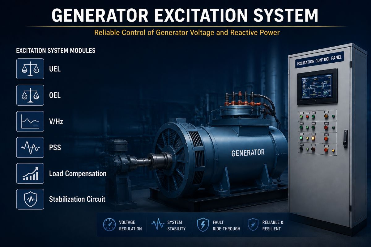
The Generator excitation system pushes DC into the generator rotor winding. This DC creates the magnetic field that, when spun by the turbine, induces an AC voltage in the stator. But simply pushing current is not enough. The excitation system must also keep the terminal voltage steady, help the grid stay calm during disturbances, and protect the costly rotor and stator from damage.
A whole team of control blocks and protection blocks does this work, each one handling a very specific job. Let us meet them, one by one.
⚠️ Limiters & Stabilizers ⚠️
| Voltage Reference | ➜ | Σ | ➜ | AVR (AC Reg) | ➜ | Exciter (power stage) | ➜ | GENERATOR field + stator |
The AC Regulator, better known as the Automatic Voltage Regulator (AVR), is the main brain, the outer loop. It senses the generator’s AC terminal voltage, compares it with a reference set by the operator, and adjusts field current up or down until the two match.
The DC Regulator is the backup inner loop. Instead of holding voltage constant, it holds the field voltage (a DC quantity) at a fixed value set by Manual action. It is used during start-up, commissioning, special tests, or whenever the AVR is out of service.
The AVR has a very high gain, so it can correct voltage errors quickly. Unfortunately, high gain combined with the slow magnetic time constant of the field winding can make the loop oscillate, just like a hyperactive thermostat that keeps overshooting.
The stabilization circuit — usually a lead-lag network taking feedback from the exciter output or field voltage — adds artificial damping. It tames the loop and lets the AVR respond fast without ringing.
When a fault, a sudden load change, or a line switching disturbs the grid, the generator rotor starts swinging back and forth against the rest of the system at low frequencies (typically 0.1 to 2 Hz). If these swings grow, the machine can lose step.
The Power System Stabilizer watches a signal that reveals the swing — usually speed deviation, frequency, or accelerating power — and feeds a supplementary signal into the AVR. By gently modulating excitation in phase with rotor speed, the PSS adds positive damping to electromechanical oscillations and keeps the generator locked with the grid.
By default, the AVR regulates voltage right at the generator terminals. With load compensation, the regulation point can be moved inside the machine or outside it:
- Droop (positive) setting: regulates a point inside the generator. Terminal voltage falls slightly as reactive load rises. This is essential when many units run in parallel — without droop, they would fight for reactive load.
- Line-drop (negative) setting: regulates a point beyond the terminals, compensating for the voltage drop across the step-up transformer or line so the grid-side voltage stays steady.
Every generator has a capability curve — a closed area on the P-Q plane where it is safe to operate. Two limiters guard the boundaries:
| ⬅ LEAD (under-excited) UEL boundary stator end-core heating & pole-slip risk | ✅ SAFE OPERATING AREA P–Q inside the capability curve | LAG (over-excited) ➡ OEL boundary rotor copper overheating |
UEL (Under Excitation Limiter): if the field current drops too low, the generator may lose synchronism (pole-slip) and the stator end-core overheats due to leading-VAR operation. The UEL raises the AVR reference whenever the operating point approaches the lower boundary.
OEL (Over Excitation Limiter): if the field current is too high for too long, the rotor copper winding burns. The OEL has an inverse-time characteristic — small overloads allowed for minutes, big overloads clamped in seconds — protecting the rotor while still allowing short emergency boosts.
Magnetic flux in the generator iron core (and in the connected step-up transformer) is proportional to Voltage ÷ Frequency. At normal speed and rated voltage, V/Hz is 1.0 pu, and flux stays in the safe zone. But during start-up, run-down, or island operation, frequency may dip while voltage stays high. If V/Hz climbs above about 1.05 to 1.10 pu, the core saturates, eddy currents skyrocket, and iron overheats — causing permanent damage.
- V/Hz Limiter: reduces excitation automatically to hold flux below the limit.
- V/Hz Protection: trips the unit if the limiter fails or the excursion is severe.
The rotor field winding is a huge inductor that stores magnetic energy ½·L·I². If the field breaker is opened suddenly with this energy trapped inside, the inductor produces a massive voltage spike (V = L·di/dt) that can punch through rotor insulation.
| Exciter (DC source) | ─ | Field Breaker | ─ | Field Winding (big inductor L) |
| ⬇ aux contact closes on trip ⬇ | ||||
| ⚡ Discharge Resistor (or Thyristor Crowbar) ⚡ connects across the field, winding to absorb stored magnetic energy | ||||
The field shorting circuit — usually a discharge resistor connected automatically across the field via an auxiliary contact of the field breaker, or a thyristor crowbar — gives the stored energy a safe path to dissipate as heat. Field current decays smoothly within a few seconds, insulation stays safe, and the machine is ready for the next start.
During normal operation, the AVR holds voltage, and the stabilization circuit keeps the loop calm. The PSS waits in the background, ready to dampen swings. Load compensation decides where voltage is held, allowing many generators to share reactive load happily.
When operating points stray, the UEL and OEL push the AVR back inside the capability curve. The V/Hz limiter guards the iron core against flux saturation, and the V/Hz protection trips if the limiter cannot cope.
When the machine must be stopped, the field shorting circuit dissipates the stored magnetic energy safely. Together, these blocks turn a raw exciter into a smart, self-protecting power source.