Exciter System Fundamentals
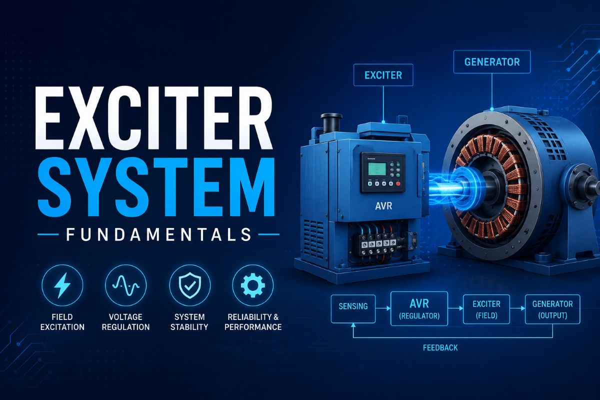
Exciter System Fundamentals- The AC exciter, pilot exciter, and exciter transformer are key components of the generator excitation system. They work together to turn the small DC control signal into a large AC exciter output, which is then rectified into the powerful DC field current that magnetizes the main generator rotor. Let’s dive into each one.
The AC exciter is a small 3-phase synchronous generator mounted on the same shaft as the main generator. Its job is to produce the high-power AC output that will be rectified into DC for the main generator field. In modern designs, the exciter has:
- Stationary field winding (stator) — carries DC from the AVR output, creating a stationary magnetic field.
- Rotating armature winding (rotor) — spins inside the stationary field, has 3-phase AC induced in it. This is the exciter’s high-power AC output.
| Stationary Field (DC) Fed by AVR | → | Rotating Armature Generates 3-phase AC |
The exciter’s AC output voltage is proportional to the AVR’s field current. So by controlling the small DC signal into the exciter field, the AVR can control the large AC output. This output is then fed to either a stationary or rotating rectifier.
The pilot exciter (also called the permanent magnet generator, or PMG) is a small AC generator with a permanent-magnet rotor. It’s mounted on the same shaft as the AC exciter and main generator. The pilot exciter has two key jobs:
- Supply startup power — when the machine is starting up, and there’s no residual magnetism in the exciter field, the pilot exciter provides the initial AC power to get the excitation system going.
- Feed the AVR — the pilot exciter’s constant-frequency AC output powers the AVR electronics, providing a stable supply isolated from grid disturbances.
| Permanent Magnet Rotor No power needed | → | AC Stator Feeds AVR & provides startup power |
So the pilot exciter is a small but critical player — it jump-starts the whole excitation system and keeps the AVR powered up through any grid event. Without it, the excitation system would need a separate station battery for startup and AVR power.
In static excitation systems (where the rectifiers are stationary), the exciter transformer sits between the Generator terminal voltage or auxiliary bus and the rectifier input. It has two key functions:
- Step down the AC voltage from the Generator voltage or auxiliary bus voltage to a level the rectifier components can handle (typically <500V).
- Isolate the exciter from the rectifier, preventing any faults or transients on the rectifier side from propagating back to the exciter windings.
| Exciter 3-phase AC Higher voltage | → | Transformer Steps down, isolates | → | Rectifier Input Lower voltage AC |
In rotating rectifier systems, there’s no exciter transformer — the exciter AC feeds the rectifiers directly because both are on the rotor. But in stationary systems, the transformer is a key safety and matching element between the exciter and the frame-mounted rectifiers & AVR.
The excitation system’s power flow goes like this:
- The pilot exciter generates the initial power to start the system and feeds the AVR.
- AVR sends a small DC control signal to the AC exciter field.
- The AC exciter generates a powerful 3-phase AC output proportional to the AVR input.
- Exciter transformer (if present) steps the voltage down and isolates the rectifier.
- Rectifiers convert the exciter AC into DC for the main generator field.
- The main generator field produces the rotating magnetic field, inducing AC power in the stator.
So it’s a multi-stage amplification and conversion chain, turning the AVR’s small control signal into the huge DC field current that drives the generator’s output. The AC exciter, pilot exciter, and exciter transformer are the unsung heroes enabling this critical transformation.