Electric Welding
Basics of Electric Welding
Electric welding is a broad category of manufacturing processes that use electrical energy to join pieces of metal together. The two primary subcategories are arc welding and resistance welding. In arc welding, an electric circuit is established to create an intense arc across an air gap between an electrode and the base metal, reaching temperatures high enough to melt both the base metal and a filler material. The molten pool then solidifies, fusing the parts together.
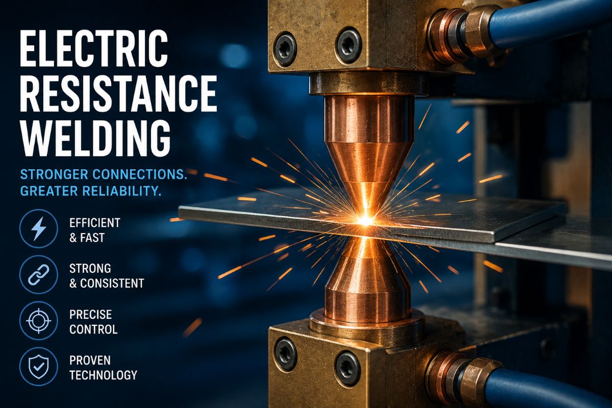
Resistance welding, by contrast, does not use an electric arc, nor does it require shielding gas or filler metal. Instead, it uses the inherent electrical resistance of the base metals to generate heat. A strong electric current is forced through the metal pieces while heavy mechanical pressure is applied. The heat generated at the interface (faying surfaces) melts the metal, and the applied pressure forges the parts together into a solid weld nugget as it cools. Because the process is localized and entirely thermoelectric, resistance welding is exceptionally clean, fast, and highly suited to automated manufacturing.
Components of Resistance Welding Systems
A typical resistance welding system (such as a spot welder) requires three main subsystems: the electrical circuit, the mechanical system, and the control system.
The mechanical system consists of the welding head and pneumatic or hydraulic cylinders that hold the metal tightly between the electrodes. The electrodes, usually made of copper alloys, must conduct the massive welding current to the workpiece, apply the physical forging force, and subsequently extract the heat rapidly from the weld zone so the nugget can solidify quickly.
The electrical circuit consists of a heavy-duty, step-down welding transformer. Resistance welding requires extremely high current (often thousands of amperes) but very low voltage. The transformer converts the standard high-voltage factory line power in the primary circuit down to low-voltage, high-amperage power in the secondary circuit. To handle the massive power switching required in the primary circuit, industrial welders rely on heavy-duty electronic switches known as line contactors.
Ignitron Tubes and SCR Line Contactors
The power flowing into the primary side of the welding transformer must be turned on and off extremely fast—often for just fractions of a second—to control the precise amount of energy delivered to the weld. Mechanical switches cannot survive this high-speed, high-current switching, so electronic line contactors are used.
Historically, ignitron tubes were the industry standard for this task. An ignitron is a specialized gas-discharge tube consisting of a sealed steel jacket containing an anode and a pool of liquid mercury that acts as the cathode. It conducts current only when a command signal is injected into its igniter. Ignitrons act as rectifiers, meaning current only flows one way. Therefore, to control the alternating current (AC) of a factory power line, two ignitrons are wired in a back-to-back configuration so that both halves of the AC wave can flow uninterrupted into the welding transformer when commanded.
Today, modern systems have largely replaced ignitron tubes with Silicon-Controlled Rectifiers (SCRs). An SCR is a solid-state semiconductor device that functions similarly to an ignitron but without the mercury, mechanical fragility, or gas-ionization delays. Like ignitrons, SCRs are paired back-to-back to act as solid-state line contactors, turning the primary current on and off instantly without any moving parts.
Heat Control Circuits and Sequence Timers
Applying the raw power is not enough; the power must be precisely timed and modulated. This is achieved through the heat control circuit and the sequence timer.
The heat control circuit (often called phase-shift control) adjusts the actual magnitude of the welding current. Instead of turning the SCR or ignitron contactors on for the full duration of every AC electrical cycle, the heat control circuit introduces a slight delay (a predetermined firing angle) in every single cycle. By delaying the firing, the contactor only passes a portion of the electrical wave to the transformer, effectively reducing the total heat generated at the weld without needing to physically change the transformer’s wire taps.
The sequence timer controls the chronological phases of the machine’s operation. A complete resistance weld occurs in a precise sequence of timed intervals, typically measured in electrical cycles. (where one cycle is 1/50th of a second on a 50 Hz grid)
Squeeze Time: The time allotted for the mechanical electrodes to clamp down on the metal and build up the required physical pressure before the electricity is turned on.
Weld Time: The exact duration the primary line contactor allows the current to flow, melting the metal at the interface.
Hold Time: The current is shut off, but the electrodes remain clamped, maintaining heavy pressure while the molten metal nugget cools and solidifies.
Off Time: The electrodes retract, releasing the finished part, and the machine resets for the next cycle.
By tying the heat control circuit and the sequence timer together, operators can guarantee that every single weld receives the same heat, pressure, and duration, allowing for perfect repeatability.
Advantages and Disadvantages of Resistance Welding
Resistance welding offers several distinct advantages that make it dominant in mass production. First, it is incredibly fast, with most welds taking less than a second to complete. Second, it does not require consumable filler materials, flux, or expensive shielding gases, lowering the cost per weld. Third, because the process is entirely contained between the electrodes and controlled by precise timers and SCRs, it is easily automated and requires very little specialized operator skill compared to manual arc welding. Finally, the process is very clean, producing little to no spatter or fumes.
However, resistance welding has several notable disadvantages. The equipment is bulky, heavy, and very expensive due to the massive transformers, SCR contactors, and copper mechanical systems required. Unlike portable arc welders, resistance welders are generally stationary machines fixed to a factory floor. Furthermore, resistance welding is generally limited to overlapping sheet metals (lap joints) and cannot be used for complex structural corner joints or thick metal plates that arc welding handles easily.
Industrial Applications
Resistance welding is the backbone of the sheet metal manufacturing industry. Its most famous application is in the automotive industry; a modern car chassis contains thousands of individual resistance spot welds holding the stamped steel body panels together. Because sequence timers and SCRs can complete a perfect weld in milliseconds, robotic arms equipped with spot welding guns can assemble car bodies at rapid speeds.
Beyond spot welding, resistance seam welding (where the electrodes are rotating copper wheels rather than stationary pins) is used to create continuous, air-tight, and liquid-tight seals. This variation is widely used in manufacturing fuel tanks, chemical drums, radiators, and domestic appliances like washing machines and refrigerators. Projection welding, another variant, is used to weld small nuts, bolts, and mounting studs directly onto sheet metal plates for electronics enclosures and automotive brackets.
By utilizing advanced solid-state SCR contactors and precise electronic timing, resistance welding transforms raw electrical energy into a rapid, highly controlled manufacturing process capable of joining millions of parts with flawless consistency.