
HVDC Converter Circuits
At the heart of every LCC-HVDC converter station is the three-phase fully controlled bridge — a circuit of six thyristors that converts AC to DC by switching each phase in a controlled sequence. The performance of that conversion — how smooth the DC voltage is, how much harmonic distortion is injected into the AC network — depends critically on one design choice: the pulse number. Understanding why every modern HVDC project uses a 12-pulse configuration, and what that means electrically, is fundamental to understanding how HVDC actually works.
The Three-Phase Fully Controlled Bridge
The Graetz bridge uses six thyristors in two groups of three — an upper group connected to the positive DC bus, and a lower group connected to the negative bus. At any instant, one upper and one lower thyristor conduct, creating a path between the AC supply and the DC circuit. Conduction transfers from thyristor to thyristor as the AC voltages rotate — a process called commutation.
Each thyristor fires after a deliberate delay — the firing angle α — measured from the natural commutation point. By controlling α, the converter regulates its mean DC output voltage: Vd = Vd0 cos α − ( 3/π) Xc Id.
Commutation voltage drop ( 3/π) Xc Id due to AC system reactance Xc at DC Id. When α exceeds 90°, the DC voltage reverses — the converter inverts, absorbing power from the DC line and returning it to the AC network.
(The DC output voltage of an HVDC converter is mainly affected by two things:
1️⃣ Firing Angle (α)
This is the delay you apply before turning on the thyristors.
- When the firing angle increases, the converter produces less DC voltage.
- When the firing angle decreases, the converter produces more DC voltage.
So the firing angle directly controls how much DC voltage the converter can generate.
2️⃣ Commutation Overlap (μ)
Commutation overlap happens because the converter transformer has reactance. Reactance slows down the transfer of current from one valve to the next. During this short overlap period, two valves conduct at the same time, which causes a loss of DC voltage.
This voltage loss depends on:
- The reactance of the converter transformer
- The DC flowing through the converter
Higher current → more overlap → more voltage drop.
⭐ Putting it all together
The actual DC voltage of the converter is simply:
- The ideal DC voltage is reduced by the firing angle,
- Further reduced by the voltage drop caused by commutation overlap.
So the converter never gives the ideal voltage; it always gives a slightly lower value because of these two effects.)
The single three-phase bridge produces a DC voltage that pulses six times per AC cycle — hence “6-pulse.” Its DC ripple magnitude is approximately 14% of the mean voltage at α = 0°, and it injects AC harmonics at orders 5, 7, 11, 13, 17, 19… into the AC network. The 5th harmonic alone is 20% of the fundamental current — far too high for any public AC grid to accept.
Pulse Number and Harmonic Orders
The pulse number p of a converter is the number of DC voltage peaks per AC cycle. It governs both the DC ripple frequency (p × f) and the lowest harmonic order injected into the AC supply (p − 1 and p + 1). Higher pulse numbers mean higher-frequency, lower-amplitude ripple on the DC side, and higher-order, smaller harmonics on the AC side — both highly desirable.
The 12-Pulse Converter: Circuit Diagram
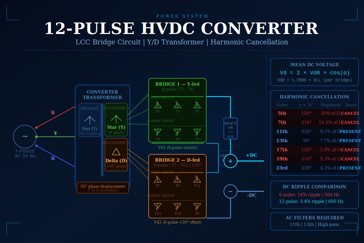
The 12-pulse converter connects two identical six-pulse Graetz bridges in series on the DC side. Both bridges are fed from the same converter transformer, whose secondary has two sets of windings — one in star (Y) and one in delta (D). The delta winding introduces a 30° phase shift relative to the star winding. This is the single topological change that transforms the converter from 6-pulse to 12-pulse.
How the 30° Shift Cancels Harmonics
Each 6-pulse bridge injects AC harmonics at orders 5, 7, 11, 13, 17, 19… The delta secondary voltage is 30° ahead of the star secondary. For any harmonic of order n, the delta bridge’s harmonic is phase-shifted by N × 30° relative to the star bridge’s harmonic. When both bridges’ harmonic currents are referred to the transformer primary and summed, those where N × 30° ≡ 180° cancel — and those where N × 30° ≡ 0° reinforce:
The 5th and 7th harmonics — which would each be 20% and 14% of the fundamental in a single 6-pulse bridge — are eliminated in a balanced 12-pulse group. The total AC harmonic distortion (THD) drops from approximately 31% (6-pulse) to 15% (12-pulse). The DC ripple shrinks from 14% to 3.4% and doubles in frequency to 600 Hz, making it far easier for the smoothing reactor to suppress. The 12-pulse converter achieves all this with just one additional winding on the converter transformer — the most cost-effective harmonic reduction possible.
Conclusion: The 30° Shift That Changed Everything
The 12-pulse converter is the universal standard for LCC-HVDC because it delivers a decisive improvement in both DC ripple and AC harmonic performance at minimal additional cost. Two Graetz bridges, one star-connected transformer secondary, one delta — and the 30° phase displacement between them does the rest. The 5th and 7th harmonics disappear. The DC voltage waveform becomes far smoother. The AC filter banks required are smaller and cheaper. Every HVDC project from the Rihand–Delhi bipole to the Changji–Guquan ±1,100 kV link depends on this single elegant topological choice.





