
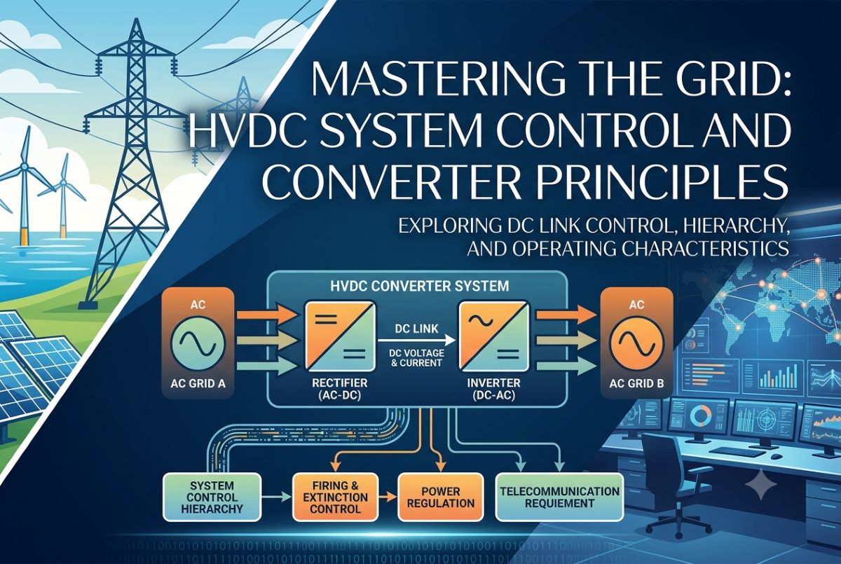
HVDC System Control and Converter Principles
Mastering the Grid: The Ultimate Guide to HVDC System Control and Converter Principles
HVDC System Control-High-Voltage Direct Current (HVDC) technology is the backbone of modern, long-distance energy transmission. Whether it’s integrating massive offshore wind farms, connecting asynchronous grids, or transmitting power across thousands of miles with minimal losses, HVDC systems are a marvel of electrical engineering.
But how do we control a system that manages gigawatts of power traveling at the speed of light? The secret lies in the sophisticated, multi-layered control systems that regulate converters, manage faults, and optimize power flow. Let’s dive deep into the principles, characteristics, and hierarchies that make HVDC system control work.
1. Principles of DC Link Control
At its core, controlling an HVDC link is about managing two fundamental variables: Direct Current (Idc) and Direct Voltage (Vdc). Because power is the product of voltage and current (P = Vdc × Idc), controlling these two elements allows us to precisely dictate how much power flows from one end of the link to the other.
An HVDC link typically consists of a Rectifier (which converts AC to DC) and an Inverter (which converts DC back to AC), connected by a DC overhead line, underground cable, or submarine cable.
The Basic Governing Equations
To understand the control principle, we look at the equivalent circuit of a line-commutated converter (LCC) DC link. The average DC voltage of a converter can be expressed using standard algebraic terms for the web:
Where:
- Vdo is the ideal no-load DC voltage.
- α is the firing angle (for the rectifier).
- Xc is the commutation reactance.
- Idc is the DC current
For the inverter, it is more practical to express the voltage in terms of the extinction angle (γ):
Why Constant Current and Constant Voltage?
If both ends tried to control voltage simultaneously, a tiny mismatch in grid conditions would cause massive, destructive current spikes due to the very low resistance of the DC line (Rdc). To prevent this, the HVDC system uses a distinct division of labor:
- One station controls Voltage (typically the Inverter).
- The other station controls Current (typically the Rectifier).
2. Converter Control Characteristics
The interaction between the rectifier and inverter is best visualized by the classic HVDC Converter Control Characteristics (often called the Vdc-Idc operating diagram).
Vdc ^
    |       Rectifier Characteristic (Constant Current)
    |       |
    |  +----+------------------------+
    |  |    |                        |
    |  |    |<- Current Margin (Id) ->|
    |  |    |                        |
    +--+----+------------------------+-----> Idc
       |    |                        |
       |    Inverter Characteristic (Constant Extinction Angle / Voltage)
Rectifier & Inverter Dynamics
The rectifier normally operates in Constant Current (CC) mode. If the DC current drops below the reference value, the controller decreases α, boosting the DC voltage to push more current through. There is a physical limit: α cannot go below roughly 5° to 10° to ensure proper thyristor firing.
The inverter normally operates in Constant Extinction Angle (CEA) or Constant Voltage (CV) mode. It aims to keep the extinction angle γ at a safe minimum (typically 15° to 18°) to prevent commutation failure while maximizing efficiency.
3. System Control Hierarchy
Managing an HVDC station requires a structured, multi-tiered control architecture. This prevents low-level hardware components from being overwhelmed while allowing system operators to input macro-level commands.
| Hierarchy Level | Control Domain | Response Time | Primary Function |
|---|---|---|---|
| Level 1: System Level | EMS / SCADA | Minutes to Hours | Dispatches power orders based on market conditions and load schedules. |
| Level 2: Master Control | Coordination of Stations | Milliseconds | Coordinates active/reactive power and manages bipole balance. |
| Level 3: Converter Control | Individual Valve Bridge | Microseconds | Calculates exact firing angles and processes closed-loop current control. |
| Level 4: Firing Control | Thyristor/IGBT Gates | Nanoseconds | Converts angular electrical degrees into physical optical/electrical gate pulses. |
4. Firing Angle Control
The fundamental mechanism for manipulating converter behavior is Firing Angle Control. By delaying the moment at which a valve begins to conduct relative to the AC voltage zero-crossing, the controller regulates the average DC output.
Individual Phase Control (IPC) vs. Equidistant Pulse Control (EPC)
Early systems used IPC, which tracked each phase independently. However, if the AC grid voltage became distorted, the zero-crossings shifted unevenly, creating harmful non-characteristic harmonics.
Modern systems universally use EPC. Instead of looking at individual phase zero-crossings, a Phase-Locked Loop (PLL) synchronizes with the fundamental frequency of the AC grid and generates firing pulses at rigid, perfectly symmetric intervals (e.g., 60° for 6-pulse, 30° for 12-pulse systems). This drastically stabilizes the system under weak or unstable AC grid conditions.
5. Current and Extinction Angle Control
Current Control (CC): The Current Controller is typically a fast-acting Proportional-Integral (PI) controller. It continuously measures actual line current and compares it against the requested current order. Because the loop resistance of a DC line is incredibly small, the current controller must react within 10 to 20 milliseconds to prevent overcurrent events during line transients.
Extinction Angle (γ) Control: In line-commutated converters, a thyristor requires a brief period of reverse voltage to turn off completely. This duration is the extinction angle. If γ drops too low (below 15°), the valve fails to regain its blocking capability before forward voltage returns, causing a Commutation Failure. The CEA controller monitors this closely and adjusts the inverter advance angle automatically to protect the system.
6. Starting and Stopping of the DC Link
Bringing a multi-gigawatt HVDC link online or shutting it down safely requires an automated sequence to avoid thermal shocks and severe voltage surges.
The Sequence Steps:
- De-blocking preparation: AC breakers close, energizing the converter transformers. AC filters are switched on.
- Inverter De-blocking: The inverter is unblocked first, establishing its voltage-blocking capability.
- Rectifier De-blocking: The rectifier is unblocked with a high firing angle (α ≈ 90°), outputting zero initial DC voltage.
- Voltage & Current Ramping: The rectifier angle is smoothly reduced, charging the line up to full voltage, and current is ramped to the desired schedule.
- Stopping: To stop, power is ramped down, and the rectifier firing angle is forced deep into the inverter region to drive the current rapidly to zero before the system blocks the valves completely.
7. Power Control and Higher-Level Controllers
While basic loops look at current and voltage, operators regulate Active Power (P) and Reactive Power (Q). Higher-level controllers sit atop the basic loops to translate macro demands into real-time current and voltage updates.
Features like the Voltage Dependent Current Order Limiter (VDCOL) protect the grid. If a major fault drops the system voltage, the VDCOL automatically cuts the allowed current order, preventing grid collapse. Furthermore, modern links use specialized Frequency Control and Power System Stabilizers (PSS) to modulate active power and instantly damp out dangerous electromechanical oscillations across interconnected grids.
8. Telecommunication Requirements
For an HVDC link to function seamlessly, the rectifier and inverter stations must talk to each other continuously via real-time data streaming links.
High-performance protection signaling requires telecommunication systems with a latency of under 5 to 10 milliseconds, supported by fully redundant Fiber Optic (OPGW) channels.
If all telecommunications completely fail, the system is designed not to collapse. Both stations instantly shift into an Emergency Autonomous Control Mode, using pure local sensor measurements and pre-programmed safety parameters to keep power moving steadily until communication channels are restored.





