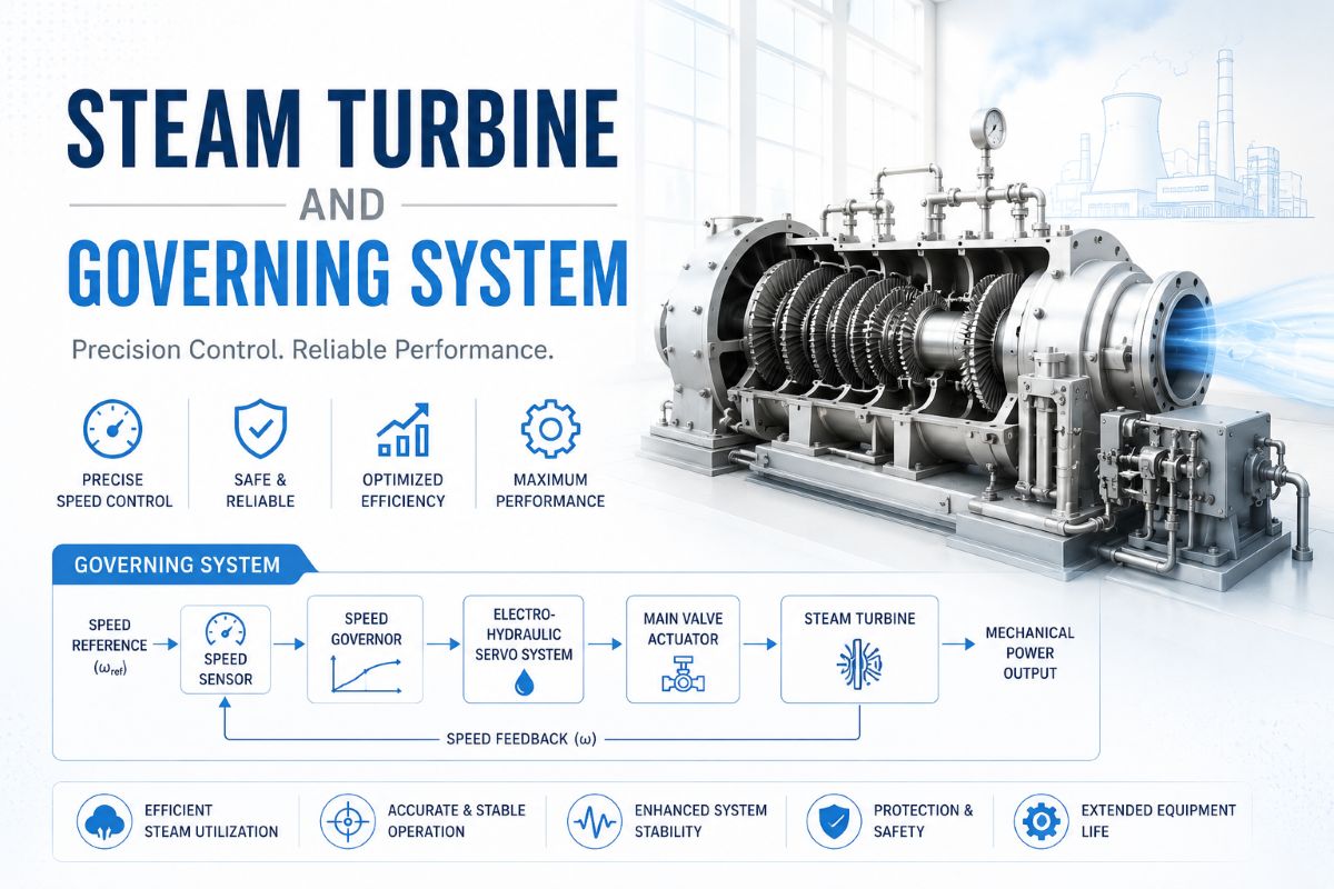
Steam Turbine and Governing System
Steam Turbine and Governing System
Modelling of Steam Turbine and Governing System
Steam turbines are the workhorses of large-scale thermal power generation, driving more than half of the world’s installed synchronous generator capacity. Unlike hydraulic turbines, the working fluid in a steam turbine is highly compressible, and the dynamics of steam flow through multiple turbine stages, reheaters, and crossover piping introduce distinctive time constants that shape the mechanical power response. Accurate modelling of the steam turbine and its governing system is essential for load-frequency control studies, transient stability analysis, and the design of supervisory controls that protect both the turbine-generator and the boiler.
Fundamental Concept of Steam Turbine Operation
A steam turbine converts the thermal energy of high-pressure, high-temperature steam into mechanical shaft power through a series of stationary nozzles and rotating blades. Steam enters the turbine at the throttle through control valves, expands across multiple stages, and exhausts to a condenser at near-vacuum pressure. The mechanical power developed depends primarily on the steam flow rate, the inlet conditions (pressure and temperature), and the expansion ratio across each stage.
Modern large steam turbines for power generation are typically configured as tandem-compound or cross-compound arrangements with multiple turbine sections — a high-pressure (HP) section, an intermediate-pressure (IP) section, and one or more low-pressure (LP) sections. Between the HP and IP sections, steam is returned to the boiler reheater, where it is reheated to near the original inlet temperature before re-entering the IP turbine. This reheat cycle improves overall plant efficiency but introduces a significant additional time delay into the power response.
Steam flow into the turbine is regulated by control valves (also called governor valves or main steam valves). Additional intercept valves are located between the reheater and the IP turbine to provide rapid power reduction during overspeed events, since closing only the main control valves would still leave a large mass of steam in the reheater available to drive the IP and LP sections.
Modelling of Steam Turbines
Steam turbine models for power system studies are based on the IEEE Committee Report on dynamic models for steam and hydro turbines, which classifies turbines according to their configuration. The model represents each turbine section (HP, IP, LP) as a first-order transfer function characterised by a time constant that captures the steam volume effects in the casing and downstream piping. The mechanical power output of each section is proportional to the fraction of total turbine power developed in that section.
Steam Chest Time Constant (TCH): The steam chest is the volume between the control valves and the first-stage HP turbine nozzles. When the control valve position changes, the steam flow through the HP turbine does not change instantaneously because the steam chest volume must first fill (or empty) to establish the new pressure. The steam chest time constant is typically in the range of 0.2 to 0.5 seconds.
Reheater Time Constant (TRH): The reheater contains a large volume of steam at intermediate pressure. Following a change in HP turbine flow, the IP turbine flow lags significantly because the reheater volume must equilibrate to the new pressure. The reheater time constant is the dominant time constant in the steam turbine model, typically in the range of 4 to 11 seconds, and it is the primary reason why reheat steam turbines exhibit relatively slow power response to governor commands.
Crossover Time Constant (TCO): The crossover piping connects the IP turbine exhaust to the LP turbine inlet. Its time constant is typically 0.3 to 0.5 seconds.
Power Fractions: The total mechanical power is the weighted sum of the contributions from each turbine section. For a typical reheat unit, the HP section develops about 30% of the rated power (FHP ≈ 0.3), the IP section about 40% (FIP ≈ 0.4), and the LP section about 30% (FLP ≈ 0.3). These fractions sum to unity and are critical for accurate transient simulation because they determine how the initial power response is distributed across the fast-responding HP path and the slower IP/LP path that depends on the reheater dynamics.
The overall transfer function from control valve position to mechanical power is a combination of these fractions and time constants, with the HP power following the steam chest dynamics and the IP/LP power lagging due to the reheater time constant. This structure correctly predicts the characteristic two-phase power response: a rapid initial change (HP fraction) followed by a slower secondary change (IP + LP fractions) as the reheater pressure adjusts.
Steam Turbine Control
Steam turbine control encompasses the governing system that regulates speed and load, the supervisory controls that coordinate with the boiler, and the protection functions that respond to abnormal conditions. The control system positions the main control valves and intercept valves to achieve the required mechanical power output while maintaining safe operating limits.
Mechanical-Hydraulic Governors: Older units employ flyweight governors that sense shaft speed mechanically and convert speed deviation into a pilot valve displacement, which controls hydraulic actuators that position the steam valves. These governors implement a fixed droop characteristic — typically 4 to 5% — meaning a 5% frequency drop results in a 100% increase in valve opening up to the load reference setpoint.
Electro-Hydraulic and Digital Governors: Modern steam turbines use digital electro-hydraulic (DEH) governors that sense shaft speed electronically through magnetic pickups and process the signal through programmable controllers. The digital governor implements speed control, load control, valve position control, and various supervisory functions in software. Tuneable droop, dead band, and rate limits are easily configured, and the governor integrates seamlessly with the plant distributed control system.
Control Modes: Steam turbines typically operate in one of several control modes. In boiler-follow mode, the turbine valves control megawatt output directly, and the boiler adjusts firing rate to maintain throttle pressure. In turbine-follow mode, the boiler controls throttle pressure by adjusting firing, and the turbine valves regulate throttle pressure. In coordinated control mode, both the boiler and turbine work together to balance fast load response with stable pressure regulation.
Fast Valving: During severe disturbances such as nearby line faults, fast valving rapidly closes the intercept valves to reduce mechanical power input and improve transient stability. The intercept valves close in a fraction of a second and then reopen as the system recovers. This emergency control action exploits the fact that approximately 70% of the turbine power flows through the IP and LP sections downstream of the intercept valves, making them highly effective for rapid power reduction.
Key Takeaway
Steam turbine modelling is built around three dominant time constants — steam chest, reheater, and crossover — combined with power fractions for the HP, IP, and LP sections. The reheater time constant dominates the dynamic response and is the reason reheat units exhibit a two-phase power response: an immediate HP contribution followed by a slower IP/LP rise. Governing systems, whether mechanical-hydraulic or modern digital electro-hydraulic, manage steam valve positions to deliver droop-based frequency regulation, while supervisory control modes coordinate the turbine with the boiler, and intercept valves provide fast-acting emergency power reduction.