TCA 785 Single-Chip Control Circuit for Converters
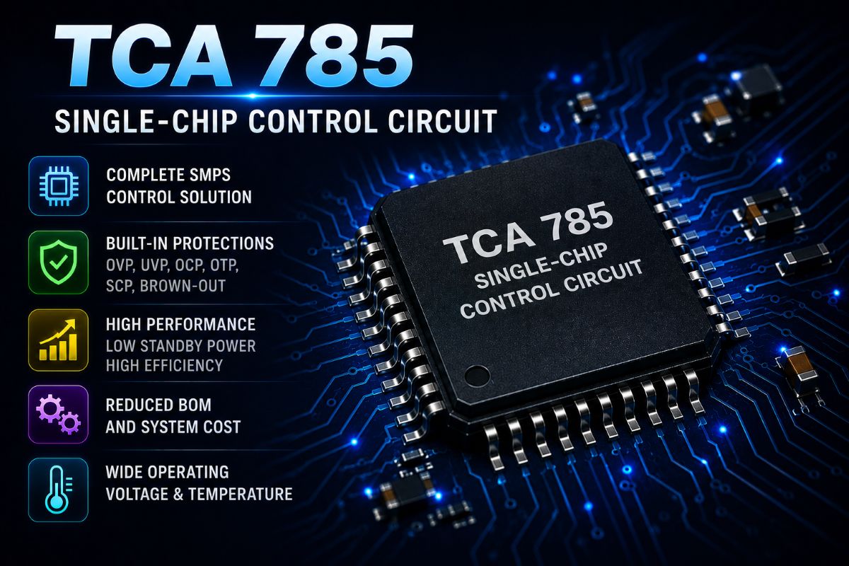
TCA 785 Single‑Chip Control Circuit for Converters provides precise phase control, synchronized triggering, and reliable firing pulse generation for modern power electronics applications.
TCA 785 Single Chip Control, Phase control IC for thyristors, TRIACs, and transistors in single and three-phase converter applications.
Introduction to TCA 785
The TCA 785 is a single-chip phase control integrated circuit designed to generate firing pulses for thyristors, TRIACs, and transistors in power converter circuits. It replaces older devices like the TCA 780 and TCA 780 D. The IC can shift trigger pulses within a phase angle of 0° to 180°, making it suitable for controlled rectifiers, AC voltage controllers, and three-phase current controllers. Because it integrates synchronization, ramp generation, logic, and output drivers, it provides a compact and reliable solution for converter control.
Operating Principle
The TCA 785 obtains the synchronization signal from the line voltage through a high-ohmic resistance at pin 5. A zero-voltage detector evaluates zero crossings and sends them to the synchronization register. This register controls a ramp generator, whose capacitor is charged by a constant current set by a resistor. When the ramp voltage exceeds the control voltage at pin 11 (which represents the triggering angle φ), the logic generates a trigger pulse. By adjusting the control voltage, the triggering angle can be shifted continuously from 0° to 180°.
Output Characteristics
- Outputs Q₁ and Q₂ provide positive pulses of about 30 µs for each half-wave.
- Pulse duration can be extended up to 180° using capacitor C12.
- If pin 12 is grounded, pulses have a duration between φ and 180°.
- Outputs Q̅₁ and Q̅₂ supply the inverse signals of Q₁ and Q₂.
- Pin 3 provides a φ + 180° signal for external logic.
- Output QZ (pin 7) gives the NOR combination of Q₁ and Q₂.
Key Pin Functions
- Pin 5: Synchronization input from line voltage.
- Pin 9 (R9): Sets constant current for ramp capacitor charging.
- Pin 10 (C10): Ramp generator capacitor.
- Pin 11 (V11): Control voltage that determines triggering angle φ.
- Pin 12 (C12): Determines pulse extension up to 180°.
- Pin 13: Extends outputs Q̅₁ and Q̅₂ to full pulse length.
- Inhibit input: Disables outputs Q₁, Q₂, Q̅₁, and Q̅₂.
Typical Applications
- Single-phase and three-phase controlled rectifiers.
- AC voltage controllers for heaters and lighting.
- Three-phase current controllers.
- Thyristor-controlled phase shifters.
- Power regulators and motor speed controllers.
Advantages
- Single-chip solution replaces multiple discrete components.
- Continuous phase control from 0° to 180°.
- Flexible pulse duration control.
- Integrated logic and output drivers.
- Reliable zero-crossing detection.
Design Considerations
When designing with the TCA 785, the control voltage must be stable and noise-free to ensure accurate firing angle. The synchronization input requires proper attenuation to avoid damaging the IC. The ramp capacitor and current-setting resistor must be selected to match the required time constant for the operating frequency. For extended pulse operation, the capacitor at pin 12 must be calculated correctly. The inhibit function can be used for safety shutdown or overcurrent protection.
Replacement with Modern ICs
Due to aging and limited availability, the TCA 785 is sometimes replaced with programmable system-on-chip (PSoC) devices that can implement the same functionality while adding digital control, ADC, and timer resources. Modern microcontrollers and dedicated gate-drive ICs also provide similar phase control capabilities with additional features like soft-start, overcurrent protection, and communication interfaces.