
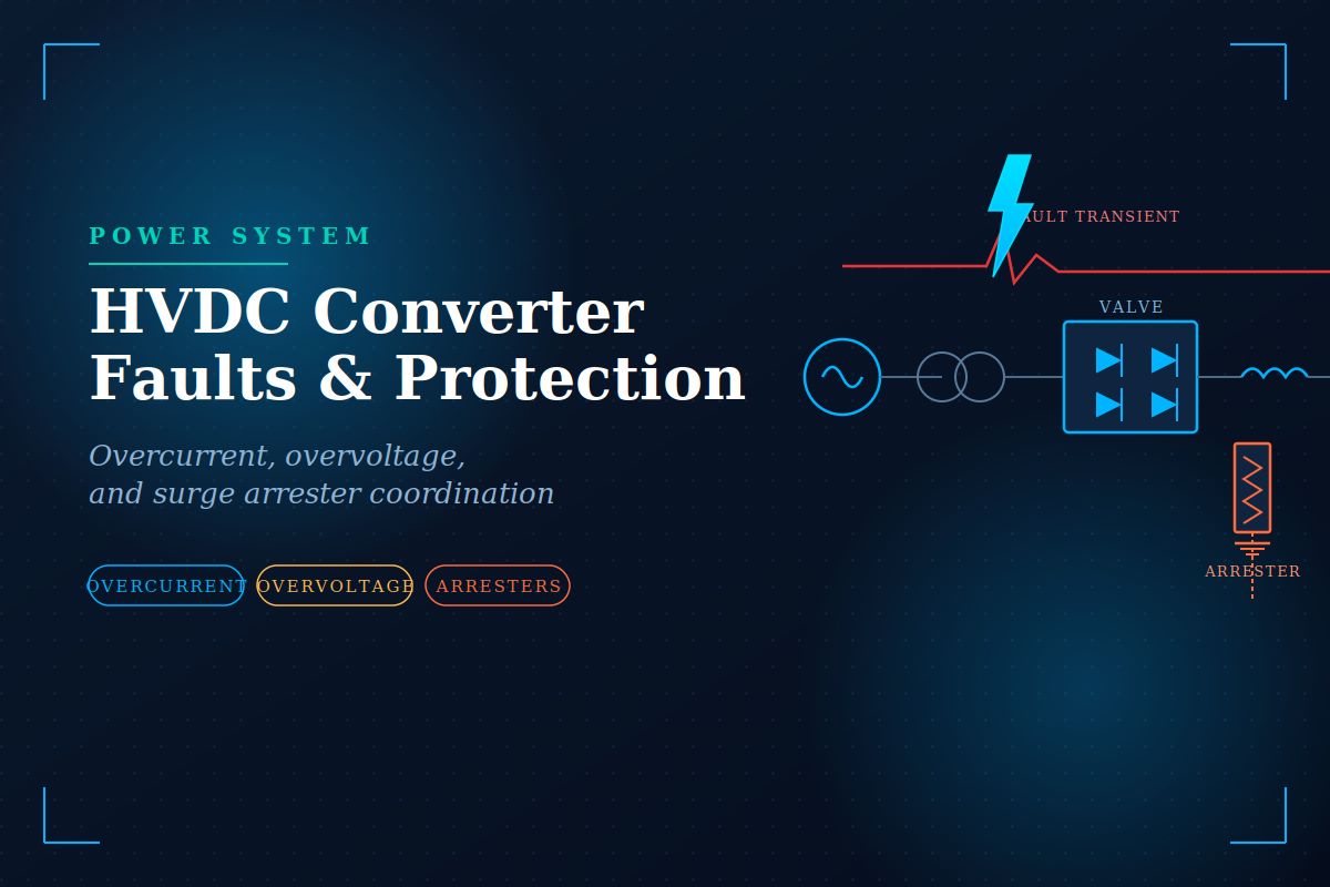
HVDC Converter Faults and Protection
HVDC Converter Faults and Protection: Overcurrent, Overvoltage, and Surge Arresters
HVDC Converter Faults and Protection-The converter station is the most electrically stressed part of any HVDC link. Thyristor valves switch thousands of amperes at hundreds of kilovolts many times per cycle, transformer windings carry harmonic-rich currents, and the DC side sees standing voltages that would flash over conventional AC insulation in microseconds. When something goes wrong — a misfire, a commutation failure, a lightning strike on the overhead line, an earth fault on the valve hall bus — the energy released can destroy semiconductor devices in less than one power-frequency cycle. Protection is therefore not an add-on but a co-design consideration that shapes valve ratings, transformer impedance, smoothing reactor size, and the entire arrester scheme.
Why is HVDC protection different? AC protection has decades of standardised practice built around circuit breakers that clear faults at a natural current zero. HVDC has no natural current zero on the DC side, semiconductor valves cannot withstand more than a few milliseconds of sustained overcurrent, and the same valves are themselves the fastest available means of controlling fault current. Protection here is a hierarchy: converter control acts first (microseconds), then valve-level bypass and blocking (milliseconds), then AC circuit breakers (tens of milliseconds), with surge arresters standing by throughout to clamp any transient the control system cannot.
Overcurrent Protection
Converter overcurrents arise from four dominant mechanisms: commutation failure at the inverter, DC line short circuits, valve short circuits (a shorted thyristor level or a flashover across a valve), and AC side faults that collapse the commutating voltage. Each has a distinct current signature and time scale, and the protection must recognise which one is unfolding before deciding how to intervene.
The first line of defence is the converter control itself. When DC exceeds a threshold — typically 1.5 to 2.0 per unit — the current controller ramps up the firing angle at the rectifier or forces the inverter into rectifier operation, driving the DC voltage negative and extinguishing the fault current within one to two cycles. This is called force retard, and it is uniquely available in HVDC because the same thyristors that carry the current also decide when it starts. No AC system can respond this quickly.
The i²t constraint. A thyristor’s short-circuit withstand is expressed as an i²t value in ampere-squared seconds. If a valve short occurs, the surge current is limited only by the transformer leakage impedance and can reach 30-40 kA peak for a few milliseconds. Protection must ensure the total i²t remains below the device rating; otherwise, the silicon fuses internally, and the valve is destroyed. This is why AC breaker clearing time — normally two to five cycles — is far too slow to protect the valve on its own; the transformer must limit the peak, and the AC breaker only clears the residual after the valves have already blocked.
For DC-side faults, a smoothing reactor of 100 to 300 mH is installed in series with each pole. It limits the rate of rise of fault current, giving the control system time to act and reducing peak stress on the valves. A dedicated DC line protection function monitors the rate of change of DC voltage and current; a sudden collapse in voltage together with a rising current is the unambiguous signature of a line fault, and the control initiates force retard within two to three milliseconds of detection.
Overvoltage Protection
Overvoltages at a converter station come from three sources: external lightning and switching surges arriving on the AC or DC overhead lines, internal switching transients caused by valve blocking or DC line energisation, and temporary overvoltages from load rejection or single-line-to-ground faults on the AC system. Each stresses insulation differently — lightning surges are steep-fronted and short (microseconds), switching surges are slower but longer (hundreds of microseconds), and temporary overvoltages last for cycles.
Insulation coordination in a converter station is far more intricate than in a conventional AC substation because the DC-side equipment sees a superposition of DC standing voltage, ripple, commutation overshoots, and any incoming transient. The permissible overvoltage at any point is defined by the weakest insulation nearby — typically the valve itself — and every surge arrester in the station is chosen to clamp below that limit with a margin of 15 to 20 per cent.
In operation. A well-coordinated arrester scheme means that during a lightning strike on the DC line, the incoming surge is clamped at the line arrester, the residual travels through the smoothing reactor, which flattens its front, and the valve arrester at the converter takes only what is left. No single arrester is expected to absorb the full energy; the scheme succeeds because each device sees a manageable share.
Surge Arresters
Modern HVDC surge arresters are gapless metal-oxide (ZnO) devices. Their voltage-current characteristic is extremely non-linear: below the protective level, they draw microamperes of leakage current; above it, they conduct thousands of amperes with almost no further voltage rise. This clamping behaviour is what makes coordinated protection possible.
A converter station typically employs a family of arresters, each optimised for its location. AC bus arresters protect the converter transformer primary. Converter unit arresters protect individual valve groups. DC bus arresters protect the pole equipment between the valve and the smoothing reactor. DC line arresters protect the smoothing reactor terminal and the outgoing line. Neutral bus arresters protect the low-voltage end of the pole. In a 12-pulse bipole with 500 kV DC, a station may contain twenty or more distinct arrester types, each with its own rated voltage, energy absorption capability, and protective level.
Critical design requirement. Arrester energy capability must be verified for the worst credible fault, not the average case. A DC line-to-ground fault near the converter can force the DC line arrester to absorb the full energy stored in the line capacitance plus any energy fed in by the control system before force retard takes effect. Undersizing here is catastrophic: the arrester fails short-circuited, converting an overvoltage event into a permanent earth fault that takes the pole out of service until the arrester is replaced.
Overcurrent control, overvoltage insulation coordination, and the arrester scheme are not three separate systems but three aspects of one integrated protection design. The valve rating, the transformer impedance, the smoothing reactor inductance, and every arrester’s rated voltage are chosen together, iteratively, until every credible fault scenario is bounded within equipment capability. This is why HVDC converter protection cannot be retrofitted or standardised the way AC feeder protection can — it is engineered into the station from the first single-line diagram.





