
High Voltage Direct Current Transmission Systems
Power System
High Voltage Direct Current Transmission Systems: Description, Types, and Applications
How high voltage direct current transmission systems are built, the configurations they come in, and the missions where they outperform AC.
What a DC Transmission System Is
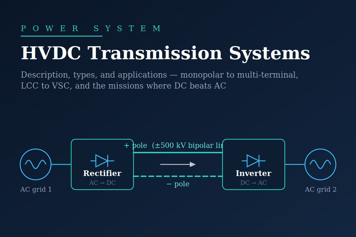
A high-voltage direct current (HVDC) transmission system moves bulk electrical power using constant, unidirectional voltage and current instead of the alternating quantities of the surrounding grid. Because generation and consumption remain overwhelmingly AC, every HVDC scheme is fundamentally a three-stage machine: a rectifier station converts AC to DC at the sending end, a DC line or cable carries the power, and an inverter station converts it back to AC at the receiving end. The physics motivating this arrangement is simple — a DC line has no reactive power flow, no charging current, no skin effect, and no synchronism requirement, so once the conversion cost is paid, the line itself is cheaper, lower-loss, and free of the stability limits that constrain long AC corridors.
A converter station is far more than the converter valves. Each terminal contains converter transformers that adapt grid voltage to the valve winding and provide the phase shifts needed for 12-pulse operation, thyristor or IGBT valve halls where the actual conversion occurs, smoothing reactors that flatten DC-side ripple and limit fault current rise, AC and DC harmonic filters that absorb the characteristic harmonics conversion produces, reactive power compensation (for line-commutated schemes), and the cooling, protection, and control systems that coordinate both ends over telecommunication links. In ground-return configurations, carefully engineered earth electrodes located kilometres from the station complete the circuit.
Foundational Concept
Power flow in an HVDC link does not follow network impedance the way AC power does — it is set directly by converter control. The rectifier typically operates in constant-current control and the inverter in constant-extinction-angle or constant-voltage control, allowing the scheduled power to be dialled in precisely and reversed in a fraction of a second.
Types by Link Configuration
1. Monopolar Link
A single high-voltage conductor with the return path through earth/sea electrodes or a metallic return conductor. It is the cheapest configuration — half the line of a bipole — and is common for submarine cable schemes. Its drawbacks are the environmental and corrosion concerns of continuous ground current and the total loss of transfer if the single pole fails.
2. Bipolar Link
Two poles at equal and opposite voltage (e.g., ±500 kV or ±800 kV) with the neutral point grounded. In normal balanced operation, the earth carries almost no current. If one pole trips, the healthy pole continues delivering up to half the rated power using ground return — built-in redundancy that makes the bipole the standard choice for major overhead transmission corridors worldwide.
3. Homopolar Link
Two or more conductors all at the same polarity (usually negative, which produces less corona and radio interference) with permanent ground return. It offers economy in insulation, but the continuous full-load earth current has limited its use to rare historical applications.
4. Back-to-Back Link
The rectifier and inverter are at the same station, with no DC line at all. Its sole purpose is interconnection — coupling two AC systems that are asynchronous or operate at different frequencies (50/60 Hz). Because there is no line, the DC voltage can be chosen low, and the valves optimised for current. India’s early regional grid interconnections used back-to-back stations before the national grid was synchronised.
5. Multi-Terminal Link
Three or more converter stations on a common DC network, either in series or parallel. Multi-terminal operation is demanding with classical thyristor technology because power reversal requires voltage polarity reversal, but modern VSC technology makes true DC grids feasible — the basis of proposed offshore wind networks and India’s ±800 kV multi-terminal schemes.
Types by Converter Technology
Line-Commutated Converters (LCC) use thyristors that rely on the AC network voltage to turn off. LCC is the mature workhorse for the very largest ratings — multi-gigawatt, ±800 kV ultra-HVDC corridors — with converter losses below 1% per station. Its costs: it consumes reactive power of roughly half the transferred power, needs a reasonably strong AC system at each end, injects harmonics requiring large filters, and can suffer commutation failure during nearby AC faults.
Voltage-Source Converters (VSC) use self-commutating IGBTs, today almost always in modular multilevel converter (MMC) form. VSC controls active and reactive power independently, connects to weak or even dead networks (black start), reverses power without polarity reversal, produces nearly sinusoidal waveforms with minimal filtering, and occupies a far smaller footprint — decisive for offshore platforms. Its historical penalties, higher losses and lower ratings have narrowed dramatically with MMC technology.
Selection Constraint
Choose LCC when the mission is maximum bulk power at minimum loss between two strong AC systems. Choose VSC when the connection point is weak, space is scarce, black-start or reactive support is required, or a future multi-terminal DC grid is envisaged.
Applications
HVDC earns its converter cost in five principal missions. Long-distance bulk transmission: beyond the 500–800 km break-even distance, DC delivers gigawatts from remote hydro, coal, or renewable clusters to distant load centres. Submarine and underground cables: beyond roughly 40–80 km, AC cable charging current consumes the entire conductor rating, so every long sea crossing is DC. Asynchronous interconnection: back-to-back and point-to-point links join grids of different frequencies or independent frequency control, trading power without merging dynamics. System stabilisation: the fast controllability of a DC link can damp power oscillations and firewall disturbances, since faults do not propagate through the DC link. Renewable integration: VSC-HVDC is the standard connection for large offshore wind farms and increasingly for long corridors evacuating solar parks.
Indian Context
India operates one of the world’s largest HVDC fleets: ±500 kV bipoles such as Rihand–Dadri and Talcher–Kolar, and ±800 kV ultra-HVDC schemes including the multi-terminal North-East Agra link and Raigarh–Pugalur (India’s first ±800 kV VSC scheme) — all carrying gigawatts across the subcontinent.
Bringing It Together
A DC transmission system is best understood as a controllable power valve inserted into the AC world: converter stations at each end pay a fixed toll in cost and complexity, and in return the line between them sheds every AC limitation — reactive power, charging current, stability angle, and synchronism. The configuration menu, from simple monopole through the redundant bipole to back-to-back couplers and emerging multi-terminal DC grids, and the technology choice between bulk-optimised LCC and flexibility-optimised VSC, let engineers match the scheme precisely to the mission. As renewable generation pushes power over ever longer distances and under ever more seas, HVDC has moved from a niche solution to a central pillar of modern grid architecture.





