
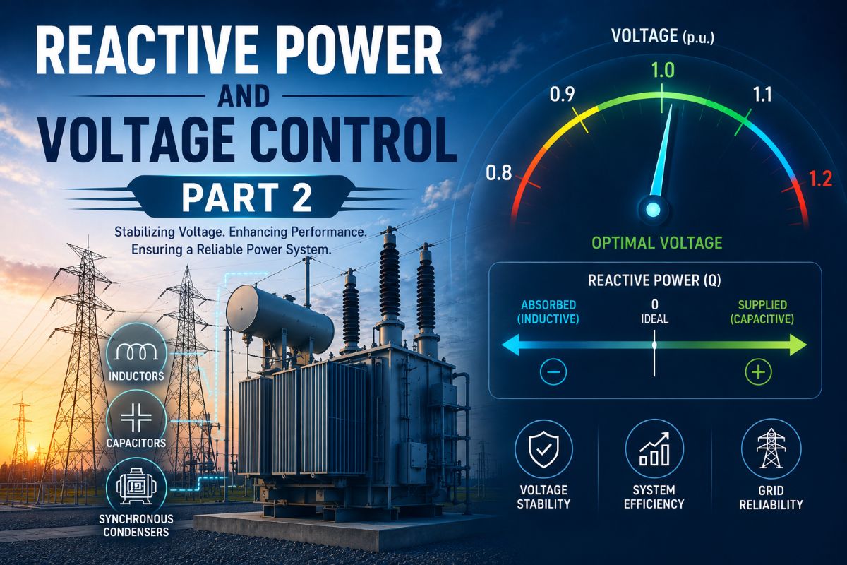
Reactive Power Control Part 2
Static VAR Systems, Transmission Compensation and Tap-Changing Control
Reactive Power Control Part 2- Switched capacitor and reactor banks correct reactive power in fixed steps, and a synchronous condenser does it smoothly, but at the cost of a rotating machine. The modern answer to controlling reactive power continuously and instantly, with no moving parts, is the static VAR system. Alongside it, transformers with adjustable taps shape the voltage profile across the network. Together, power-electronic compensators and tap-changing transformers form the backbone of practical voltage control, and understanding how they work — and how they are represented in studies — is essential to running a stable system.
Principle of Transmission System Compensation
A transmission line resists the flow of power chiefly through its series inductive reactance, and it influences voltage through its shunt capacitance. Compensation means deliberately adding reactive elements to modify these natural properties so the line behaves better. There are two broad approaches. Shunt compensation connects reactive devices from line to neutral to control the voltage at a point, supplying reactive power to lift a sagging voltage or absorbing it to pull down a rising one. Series compensation inserts reactance in line with the conductor to cancel part of the line’s own inductive reactance, electrically shortening the line and raising the power it can transfer.
Shunt compensation acts on voltage at a node; series compensation acts on the impedance between nodes. The first manages the reactive balance at a busbar, the second manages the power transfer along a corridor.
The goals are the same in either case: keep voltages within limits, reduce losses, improve power factor, and push back the stability limit so more power can flow safely. Compensation that can respond quickly also helps the system ride through disturbances, holding voltage up during faults and damping the swings that follow.
Static VAR Systems
A Static VAR Compensator (SVC) is a shunt device that varies its reactive output continuously using thyristor-controlled power electronics rather than mechanical switches. Its two basic building blocks are the thyristor-controlled reactor (TCR) and the thyristor-switched capacitor (TSC). In a TCR, the firing angle of the thyristors controls how much of each half-cycle the reactor conducts, so the effective inductive reactance — and hence the reactive power absorbed — can be varied smoothly. A TSC switches capacitor banks in and out cleanly at the instant of zero voltage across them, avoiding transients.
A common arrangement combines a TCR with fixed or switched capacitors. The capacitors supply reactive power while the TCR absorbs a controllable amount, so the net output can be adjusted continuously from fully capacitive to fully inductive. The SVC’s controller compares the measured voltage with a reference and adjusts the firing angle within milliseconds, giving fast, stepless voltage support.
A more advanced device is the STATCOM, built around a voltage-source converter rather than thyristor-switched passive elements. It synthesises a controllable AC voltage behind a small reactance; making that voltage higher than the system voltage causes it to deliver reactive power, and making it lower causes it to absorb. Its key advantage is that, unlike a capacitor-based SVC, its reactive output does not collapse as system voltage falls — it can hold up its current even at low voltage, which makes it far more effective at supporting a weak or sagging grid.
Modelling of Reactive Compensating Devices
For system studies, these devices must be reduced to manageable representations. A fixed shunt capacitor or reactor is the simplest case: it is modelled as a constant susceptance whose reactive power varies with the square of the voltage at its busbar. A series capacitor is modelled as a negative reactance inserted into the line, reducing the total series impedance used in load-flow and stability calculations.
An SVC is modelled as a variable susceptance that holds voltage at a set value while its output stays within limits, then reverts to a fixed susceptance once it hits its maximum or minimum — the so-called controlled-bus-with-limits behaviour.
In load-flow studies, a continuously controlled compensator is therefore treated rather like a generator’s voltage-control bus: it regulates voltage as long as it has reactive capacity to spare, and switches to a constant-susceptance model once saturated. For dynamic studies, the device is given a control block diagram with its gain, time constants, and limits, so the simulation captures how quickly it responds and where it runs out of range. A STATCOM is modelled similarly, but as a controlled current source that maintains output even at depressed voltage.
Application of Tap-Changing Transformers to the Transmission System
A transformer with adjustable taps can change its turns ratio and so shift the voltage from one side to the other. An on-load tap-changer (OLTC) does this without interrupting supply, stepping through tap positions to raise or lower the secondary voltage as conditions change. In transmission, tap-changers are used to keep the voltage profile across transformation stages within limits as load rises and falls through the day.
It is important to see what a tap-changer can and cannot do. It does not create reactive power; it redistributes voltage. Raising the tap to lift voltage on one side draws more reactive power through the transformer, so if the system as a whole is short of reactive power, tap-changing alone cannot fix it — and in a severe shortage, aggressive tapping can even hasten a voltage collapse by demanding reactive power the network cannot supply. Tap-changers, therefore, work best alongside genuine sources of reactive power such as capacitors and SVCs.
Modelling of Transformer ULTC Control Systems
The under-load tap-changer (ULTC) control is modelled as a discrete, time-delayed feedback loop rather than a continuous regulator. The controller measures the voltage it is meant to hold, compares it with a reference, and acts only when the error exceeds a deliberate deadband. This deadband, typically a little wider than one tap step, prevents the mechanism from hunting endlessly between adjacent positions.
Once the error stays outside the deadband for a set time delay, the controller commands one tap movement, then waits and reassesses before moving again. The model therefore carries three essential parameters: the deadband, the intentional time delay, and the step size per tap. Because each transformer waits before stepping, a chain of ULTCs across the network acts in a slow, staggered fashion. Capturing this discrete, delayed behaviour matters in long-term voltage-stability studies, where the cumulative tapping of many transformers over minutes can either restore voltages or, in a reactive-power shortage, drive the system toward collapse.
Distribution System Voltage Regulation
At the distribution level, the challenge is to deliver voltage within a tight band to every customer along a feeder, despite the voltage drop that grows with distance and load. Several tools are combined. Substation transformers with OLTCs set the voltage at the feeder head. Step voltage regulators — essentially autotransformers with tap-changers — are placed further along long feeders to boost voltage where it has sagged. Switched shunt capacitor banks supply reactive power near concentrations of inductive load, raising voltage and improving power factor at the same time.
A widely used refinement is line-drop compensation, which lets the regulator estimate the voltage at a distant load point from the current it is carrying, and hold that remote voltage steady rather than the voltage at the regulator itself.
Modern distribution adds further complexity. Rooftop solar and other embedded generation can push voltage up at the far end of a feeder, sometimes reversing the usual drop, so regulation schemes increasingly coordinate tap-changers, capacitors, and the reactive capability of inverters to keep every point on the feeder within limits.
Across transmission and distribution alike, the principle is constant: voltage is held by managing reactive power and by shaping the network’s impedance. Static VAR systems and STATCOMs supply fast, continuous reactive support; series and shunt compensation reshape what the lines can carry; and tap-changing transformers, with their deliberate deadbands and delays, trim the voltage profile stage by stage — each tool chosen for the timescale and the location where it works best.





