Power flow analysis
Power flow analysis
Power flow analysis is a steady-state study used to determine bus voltages, voltage angles, real and reactive power flows, and transmission losses in an interconnected power system under a given operating condition. It is one of the most important studies in power system planning, operation, expansion, and security assessment because it shows whether the network can supply the load within acceptable voltage and thermal limits.
In a power flow analysis, the network model is built from bus, generation, load, and transmission data, and the solution provides the system’s operating point. Typical outputs include voltage magnitude at each bus, phase angle of each bus, real and reactive power in each line, and total system losses.
This study is also called load flow analysis because it evaluates how generated power is distributed through the network to supply connected loads. Since line losses are not known in advance, the calculation must satisfy the overall power balance while meeting the specified bus conditions.
Bus classification
For load-flow studies, buses are generally classified into three main categories: load bus, voltage-controlled bus, and slack bus. The classification depends on which electrical quantities are specified and which are treated as unknowns during the solution.
In bus analysis, the common variables are real power P, reactive power Q, voltage magnitude ∣V∣, and voltage angle δ. At each bus, any two of these are usually specified, and the remaining two are calculated from the load-flow solution.
Load bus
A load bus is also called a PQ bus because real power P and reactive power Q are specified at that bus. The unknown quantities are the voltage magnitude and voltage angle, which are obtained after solving the power flow equations.
Normally, no generator is connected to a pure load bus, so only the demand is known in advance. These buses represent consumer loads such as industrial plants, commercial centers, substations, or aggregated distribution demand.
Voltage-controlled bus
A voltage-controlled bus is also called a PV bus or generator bus. At this bus, the specified quantities are real power generation P and voltage magnitude ∣V∣ , while reactive power Q and voltage angle δ\delta are unknown.
This type of bus exists where voltage is regulated, usually by a generator excitation system and an automatic voltage regulator. The prime mover controls active power, while excitation controls terminal voltage, so the bus voltage is maintained close to the scheduled value.
The term “device bus” is not a standard primary bus class in most power-flow textbooks, but buses connected to voltage-regulating devices can behave like voltage-controlled buses. A bus without a generator may still be treated as a voltage bus if a VAR-support device controls voltage by injecting or absorbing reactive power.
Slack bus
The slack bus, also called the swing bus or reference bus, is the balancing bus of the system. Its specified quantities are voltage magnitude and voltage angle, and the unknown quantities are real and reactive power generation required to balance the network.
The slack bus provides the angular reference for the entire system, so its voltage angle is usually taken as 0 degrees. It also absorbs the mismatch caused by transmission losses and numerical approximations, which is why only one slack bus is normally assigned in a load-flow study.
Representation of power network elements
For power-flow analysis, the actual three-phase power network is represented in simplified form so that calculations become manageable. The system is modeled using buses connected by network elements such as transmission lines, transformers, generators, and loads, often shown first in a one-line diagram and then converted into an equivalent electrical model.
Transmission lines are represented by their series impedance and, when needed, shunt admittance. Transformers are represented by equivalent impedance and off-nominal tap ratio if tap-changing action is considered, while loads and generators are represented as power injections or absorptions at buses.
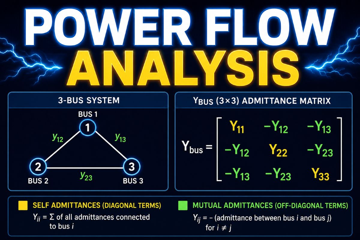
The complete network is then expressed mathematically by the bus admittance matrix, often called the YbusY_{bus} matrix, which relates bus current injections to bus voltages. This compact matrix representation forms the basis for numerical methods such as Gauss-Seidel and Newton-Raphson used in power-flow studies.
Example view
In a simple system, a generating station bus may be treated as a PV bus, an industrial receiving substation may be treated as a PQ bus, and one major grid bus is selected as the slack bus. After solving the load flow, the engineer can check whether bus voltages stay within limits, whether line loading is acceptable, and how much reactive support the system requires.