Variable Speed Drive (VSD) control methods
Variable Speed Drive (VSD) control methods
Understanding the difference between these four Variable Speed Drive (VSD) control methods comes down to how the drive manipulates the motor’s magnetic flux and torque to achieve the desired speed and dynamic response.
When managing rotating equipment in a continuous or batch manufacturing environment—such as agitators, compressors, or centrifugal pumps—selecting the correct control philosophy is critical for process stability, energy efficiency, and equipment longevity.
Here is a detailed breakdown of how each control method operates, followed by a comparative analysis.
1. Scalar Control (V/f Control or V/Hz Control)
Scalar control is the simplest and most common method for general-purpose applications. It focuses on maintaining a constant ratio between the voltage (V) and the frequency (f) applied to the motor stator.
How it Works: To maintain a constant magnetic flux in the motor, the drive increases the voltage proportionally as the frequency increases. It does not calculate or directly control the torque; torque is simply a byproduct of the motor’s natural slip.
Performance: It provides poor dynamic response and cannot precisely control speed because the actual motor speed fluctuates depending on the load. It also produces very little torque at extremely low speeds (below 5 Hertz).
Industrial Application: This is perfectly suited for variable torque applications with predictable load curves, such as cooling tower fans, blowers, and standard centrifugal water pumps. It is also the only method that allows a single VSD to run multiple motors simultaneously.
2. Field-Oriented Vector Control (FOC or Closed-Loop Vector Control)
Field-Oriented Control brings Direct Current (DC) motor performance to Alternating Current (AC) induction motors by independently controlling the magnetic flux and the torque.
How it Works: Using complex mathematics (Clarke and Park transformations), the drive decouples the three-phase alternating stator current into two independent direct current vectors: the flux-producing current and the torque-producing current. To do this accurately, the drive requires continuous, exact data regarding the rotor’s physical position and speed, which is provided by a mechanical sensor (an encoder or resolver) mounted directly on the motor shaft.
Performance: It offers exceptional precision. It provides perfect speed regulation, lightning-fast dynamic response to load changes, and the ability to hold full torque even at zero speed.
Industrial Application: Used in highly demanding applications requiring absolute precision, such as hoists, elevators, high-speed winders, or positioning machinery.
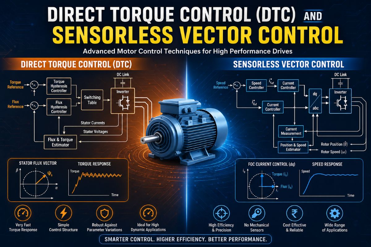
3. Sensorless Vector Control (SVC or Open-Loop Vector Control)
Sensorless Vector Control uses the exact same decoupling mathematics as FOC, but it eliminates the need for a physical encoder mounted on the motor.
How it Works: Instead of measuring the rotor position mechanically, the VSD uses a highly advanced internal mathematical model of the motor. By continuously monitoring the output voltage and the return current from the stator, the drive calculates the back-electromotive force (back-EMF) to estimate the rotor’s precise position and speed in real-time.
Performance: It provides near-FOC levels of torque and speed control without the cost or maintenance liabilities of a physical sensor. However, because back-EMF is almost nonexistent at very low speeds, the mathematical model loses accuracy below 1 or 2 Hertz, meaning it cannot reliably hold full torque at absolute zero speed.
Industrial Application: Excellent for constant torque applications operating in harsh, corrosive environments where mounting a delicate electronic encoder on a motor shaft is a reliability risk. This is highly effective for heavy batch process mixers, agitators, extruders, and positive displacement pumps.
4. Direct Torque Control (DTC)
Developed as an alternative to FOC, Direct Torque Control takes a radically different mathematical approach. It eliminates the traditional Pulse Width Modulation (PWM) modulator.
How it Works: DTC uses hysteresis comparators and a highly accurate internal motor model to estimate motor flux and torque thousands of times per second. Based on these immediate estimations, the drive directly switches the inverter’s insulated-gate bipolar transistors (IGBTs) on or off to maintain the flux and torque within predefined optimal bands. No coordinate transformations are separating current into vectors.
Performance: It provides the absolute fastest torque response time of any control method because there is no modulator delaying the signal. It handles sudden, violent load shocks brilliantly. The tradeoff is that the switching frequency is variable rather than fixed, which can introduce higher torque ripple (vibration) and acoustic noise at lower operational speeds.
Industrial Application: Best suited for extreme heavy-duty industrial applications that experience massive, sudden load impacts, such as rock crushers, large shredders, and heavy conveyors.
Comparative Summary Table
| Feature | Scalar Control (V/f) | Sensorless Vector (SVC) | Field-Oriented (FOC) | Direct Torque (DTC) |
| Control Variable | Voltage and Frequency | Decoupled Voltage/Current | Decoupled Voltage/Current | Direct Flux and Torque |
| Speed Precision | Low (Slip dependent) | High (Estimated) | Very High (Measured) | Very High (Estimated) |
| Torque Response | Slow | Fast | Very Fast | Fastest |
| Torque at Zero Speed | No | Limited | Yes (100% holding torque) | Yes (Requires high processing) |
| Encoder Required | No | No | Yes | No (Usually) |
| Multi-Motor Drive | Yes | No | No | No |
| System Complexity | Very Low | Medium | High | High |