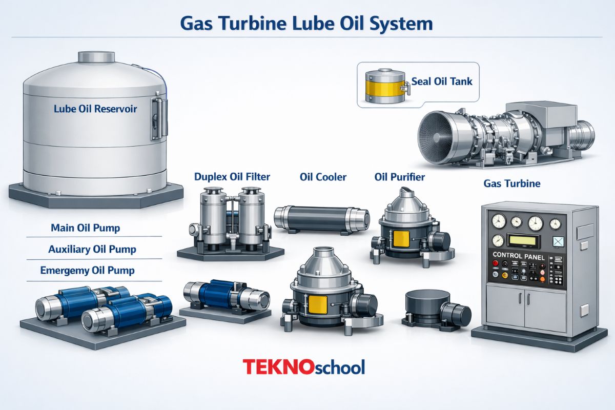
Gas Turbine Lube Oil System
Every gas turbine — whether powering a steel plant, driving a compressor, or generating megawatts of electricity — depends on one silent protector running behind the scenes: the lube oil system. Without it, even the most advanced turbine would seize within minutes. This blog takes you deep inside the gas turbine lube oil system — how it works, what it’s made of, and why every component matters.
🛢️ 1. What Is the Gas Turbine Lube Oil System?
The gas turbine lube oil system is a closed-loop, pressurized circulation system designed to continuously supply clean, cooled, and filtered oil to the turbine’s bearings, seals, couplings, and auxiliary components. Its job goes far beyond simple lubrication — it simultaneously cools, cleans, and protects every rotating and sliding interface inside the turbine train.
Gas turbines run at extremely high speeds — often between 3,000 to 20,000 RPM depending on design — generating intense heat and bearing loads. Without a reliable and fast-acting lube oil system, these conditions would rapidly destroy journal bearings, thrust bearings, and shaft seals. The lube oil system is therefore classified as a critical safety system, and its failure triggers an immediate turbine trip.
>⚙️Primary Role: Lubricate journal and thrust bearings to minimize friction and prevent metal-to-metal contact
>🌡️ Cooling Role: Carry away frictional heat generated at bearing surfaces to maintain safe metal temperatures
>🧹 Cleaning Role: Flush away wear particles, carbon deposits, and metallic debris from bearing surfaces continuously
>💧 Sealing Role: Supply oil to shaft seals to prevent hot combustion gases from leaking into the bearing compartment
>🔧 Hydraulic Role: Provide pressurized oil to hydraulic actuators for governor valves, inlet guide vanes, and turning gear mechanisms
🏗️ 2. Lube Oil System Architecture: Dry-Sump vs Wet-Sump
Gas turbine lube oil systems are broadly classified into two architectural types: dry-sump and wet-sump. The choice of architecture depends on the turbine size, application, and operational demands. Understanding this distinction is foundational before exploring individual components.
🔵 Dry-Sump System: The oil reservoir is an external tank located away from the turbine casing. Scavenge pumps actively collect oil from each bearing housing and return it to the reservoir. This design is used in large industrial gas turbines (Frame 5, Frame 7, Frame 9 class), combined cycle plants, and heavy-duty process drives. It offers superior thermal control, easier oil sampling, and greater capacity
>🟢 Wet-Sump System: Oil is stored directly within the turbine base or gearbox housing. A single pump draws oil from the sump and distributes it to bearings. This simpler design is common in smaller turbines, aeroderivative units, and fast-start backup power sets. Maintenance is simpler, but thermal control is more limited
>🔁 Closed-Loop Principle: In both systems, oil is continuously recirculated — from reservoir, through pumps, coolers, filters, bearings, and back — without any significant oil loss under normal operation
⚙️ 3. Core Components — Explained Individually
Each component in the lube oil system has a distinct and critical function. A weakness in any single component can cascade into a full turbine shutdown or, in the worst case, catastrophic bearing failure.
🛢️ 3.1 Lube Oil Reservoir (Main Tank)
The lube oil reservoir is the heart of the entire system — it stores the total oil inventory and acts as a settling and de-aeration chamber. Typical capacity ranges from 2,000 to 15,000 liters, depending on turbine rating. The reservoir is equipped with heating elements (electric or steam coil) to pre-warm the oil before startup, ensuring pumpability at low ambient temperatures.
>📏 Level monitoring: Float-type or guided wave radar level transmitters with high-high and low-low alarms wired to the ESD system
>🌡️ Temperature monitoring: Resistance temperature detectors (RTDs) in the reservoir trigger cold-oil blocking alarms and heater auto-start functions
>💨 Breather/Vent: Desiccant breathers or nitrogen blanketing prevent moisture ingress and oxidation in the oil vapor space
>🧪 Drain and sampling points: Bottom drain valves for complete draining plus dedicated sample valves for periodic oil quality analysis
⚡ 3.2 Lube Oil Pumps — Main, Auxiliary, and Emergency
The lube oil system uses a tiered pump arrangement to ensure oil supply is never interrupted — even during startup, shutdown, or a main pump failure. Each pump type is designed for a specific phase of turbine operation.
🟠Main Lube Oil Pump (MOP):
Shaft-driven by the turbine itself via a gear train — it operates only when the turbine is at or near full speed. Being mechanically driven, it is the most reliable pump during normal running as it requires no external power
>🔴 Auxiliary Lube Oil Pump (AOP): Motor-driven AC pump that operates during turbine startup and shutdown — before the shaft speed is sufficient to drive the MOP. The AOP automatically cuts in at low speed and cuts out when MOP pressure builds up
>🟡 Emergency Lube Oil Pump (EOP): Battery-backed DC motor pump that automatically starts if both MOP and AOP fail and lube oil pressure drops below a critical setpoint. It ensures bearings continue to receive oil during a rundown, preventing dry-running damage
>🔵 Turning Gear Pump / Jacking Oil Pump: A separate high-pressure, low-flow pump that injects oil at very high pressure directly under each journal bearing — used during barring/turning gear operation to hydrostatically lift the rotor and prevent bowing of the shaft during warm-up and cool-down periods
🌡️ 3.3 Lube Oil Coolers (Heat Exchangers)
Bearing friction generates enormous heat — oil returning from bearings can reach 70–90°C. The lube oil cooler reduces this temperature back to the target supply range of 40–55°C before the oil re-enters the bearing header. Two coolers are installed in parallel (2×100% arrangement) — one in service, one on standby — allowing online switchover without interrupting oil flow.
>❄️ Cooling Medium: Typically cooling water (from a closed cooling water system) or air in air-cooled heat exchangers for remote/arid locations
>🎛️ Temperature Control: A three-way temperature control valve (TCV) on the cooling water side modulates flow to maintain the lube oil outlet at the target setpoint automatically
>🚨 High-Temperature Trip: If lube oil temperature exceeds the high-high setpoint (typically 70°C at header), a turbine trip is initiated to prevent bearing damage from thin, low-viscosity oil
>📊 DP Monitoring: Differential pressure transmitters across each cooler detect fouling and signal maintenance before a performance penalty occurs
🔍 3.4 Lube Oil Filters
After the cooler, all lube oil passes through high-efficiency filters before entering the bearing header. Turbine bearing clearances are extremely tight — typically 75–150 microns — so even fine particles can cause accelerated wear or scoring of the bearing surfaces.
>🧹Filtration Rating: Cartridge-type filters with 5–25 micron absolute rating are standard in most industrial gas turbines
>🔀 Duplex Arrangement: Two filters in parallel with a transfer valve allow online filter changeover without turbine shutdown — a critical feature for continuous process plants
>📈 DP Switch: High DP alarm warns operators of filter clogging; if unaddressed, a high-high DP can trigger a turbine alarm or load reduction
>🔬 Magnetic Plugs: Magnetic inserts in filter housings capture ferrous particles and provide early warning of bearing or gear wear when inspected during maintenance
🎛️ 3.5 Pressure Control and Regulating Valves
>⚖️ Pressure Regulating Valve (PRV): Maintains a constant lube oil header pressure — typically 2.5 to 4.5 bar — by bypassing excess oil back to the reservoir. A stable pressure ensures each bearing receives its designed oil flow regardless of system variations
>🔒 Pressure Relief Valve (PSV): A safety device that opens if system pressure exceeds a preset maximum — protects pump seals, cooler tubes, and filter housings from overpressure damage
>🔁 Check Valves: Non-return valves on each pump discharge prevent backflow through idle pumps when the duty pump is running, protecting pump internals from reverse rotation
📡 4. Instrumentation, Alarms, and Trips
The gas turbine lube oil system is one of the most heavily instrumented subsystems in a gas turbine package. Every critical parameter is monitored, alarmed, and in some cases interlocked with the turbine trip circuit — because even a brief loss of lubrication at high speed can destroy bearings within seconds.
>📊Lube Oil Pressure (Low — Alarm → Trip): Pressure transmitters at the bearing header trigger a low-pressure alarm first; if pressure continues to fall below the trip setpoint, the turbine is immediately shut down. Typical trip setpoint is 1.0–1.5 bar at the header
>🌡️ Bearing Metal Temperature (RTDs/Thermocouples): Each bearing has embedded RTDs or thermocouples measuring metal temperature. A rising bearing temperature is an early indicator of oil starvation, misalignment, or contamination
>💧 Lube Oil Temperature (High — Alarm → Trip): Measured at the filter outlet/bearing header — high-high temperature trips the turbine to prevent oil oxidation and viscosity breakdown at the bearing surfaces
>🔔 Reservoir Low Level Alarm: Warns of oil loss through leakage — a critically low level will also trigger a turbine trip to prevent pump dry-running
>🔵 Vibration Monitoring: Shaft vibration probes (eddy-current type) indirectly reflect lube oil system health — rising vibration on a previously stable machine often points to bearing deterioration linked to oil quality issues
>🖥️ DCS Integration: All lube oil parameters are trended in the DCS historian — operators use trend analysis for predictive maintenance and to detect slow-developing problems before they escalate
🧪 5. Lube Oil Quality and Maintenance
A lube oil system is only as good as the oil inside it. Oil degradation is gradual and often invisible to the naked eye — but its effects on turbine reliability are devastating if left unchecked.
>🔬Oil Sampling Schedule: Oil samples should be drawn from the reservoir every 500–1,000 running hours and sent to a certified lab for viscosity, acid number (TAN), water content, particle count, and elemental analysis
>💧 Water Contamination: Water in lube oil promotes oxidation, bacterial growth, and rust formation — a coalescer or centrifugal separator (oil purifier) should run continuously, even during turbine shutdown, to remove free water
>🧲 Particle Contamination: ISO Cleanliness Level is the standard measure — most gas turbine OEMs specify ISO 16/14/11 or better. Continuous kidney-loop filtration systems help maintain cleanliness between scheduled filter changes
>♻️ Oil Change Interval: Depending on operating hours and oil condition results, a full oil drain and refill is typically done every 8,000–16,000 hours — always after flushing the system with a compatible flush oil
>🛡️ System Flushing: After major maintenance or oil change, a high-velocity oil flush at elevated temperature is mandatory to dislodge debris, weld spatter, and scale from pipework before returning the turbine to service
🚨 6. Common Problems and Troubleshooting Guide
>🔴Low Lube Oil Pressure at Header: First check AOP/MOP running status, then inspect pressure regulating valve operation, check for filter high DP, and inspect suction strainers for blockage
>🌡️ High Lube Oil Temperature: Verify cooling water flow to cooler, check TCV operation and calibration, inspect cooler for fouling or tube blockage, confirm oil viscosity grade is correct for ambient conditions
>📈 Rising Bearing Metal Temperature (Single Bearing): Indicates localized oil starvation or bearing damage — inspect bearing oil supply nozzle for blockage, check bearing clearance during next outage, and review vibration trends
>💧 Water in Lube Oil (Milky Appearance): Immediately start the oil purifier, identify the source (cooler tube leak is common), take an oil sample to the lab, and plan for partial or full oil drain if water content exceeds 0.1%
>🔁 AOP Not Cutting Out After Startup: Check MOP outlet pressure — if MOP pressure is not building, inspect the shaft-driven gear train, verify speed signal to changeover logic, and check AOP pressure switch setpoints
>⚠️ Frequent EOP Start on Rundown: Indicates MOP or AOP is not maintaining pressure during the coast-down phase — check for a stuck-open PRV, worn pump internals, or logic sequencing error in the turbine control system