
Microcontrollers Output Interfaces: FET Output vs TRIAC Output
Microcontrollers Output Interfaces: FET Output vs TRIAC Output
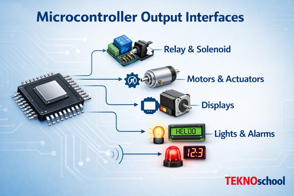
Microcontrollers inherently operate at low voltage (typically 3.3V or 5V) and low current levels, whereas industrial and practical loads often require higher voltage and current. To bridge this gap, output interfacing devices such as Field Effect Transistors (FETs) and TRIACs are widely used. Each serves distinct application domains—primarily DC and AC load control, respectively.
1. FET Output Interface (DC Load Control)

A FET, especially a MOSFET (Metal-Oxide-Semiconductor Field-Effect Transistor), is a voltage-controlled device used extensively for switching and amplification. In microcontroller applications, logic-level N-channel MOSFETs are most common.
Working Principle
The microcontroller output pin drives the gate terminal of the MOSFET. When the gate-source voltage (Vgs) exceeds the threshold voltage, the MOSFET turns ON, allowing current to flow between drain and source, thus energizing the load.
Key Characteristics
- Voltage-controlled device (minimal gate current required)
- High switching speed
- Low ON resistance (Rds(on)) → high efficiency
- Suitable for PWM (Pulse Width Modulation)
Typical Applications
- DC motor control
- LED dimming
- Relay driving
- Battery-powered systems
Design Considerations
- Use logic-level MOSFETs compatible with 3.3V/5V gate drive
- Include a flyback diode for inductive loads
- Gate resistor (≈100Ω) to limit inrush current
- Proper heat sinking for high current loads
Advantages
- High efficiency and fast switching
- Long life (no mechanical wear)
- Ideal for low-voltage DC systems
Limitations
- Not suitable for direct AC switching
- Sensitive to static (ESD)
2. TRIAC Output Interface (AC Load Control)


A TRIAC (Triode for Alternating Current) is a bidirectional semiconductor device used to control AC power. It is commonly triggered using an opto-isolator such as MOC3021 for safe interfacing with microcontrollers.
Working Principle
When a triggering pulse is applied to the gate, the TRIAC conducts in both directions during the AC cycle. Once triggered, it remains ON until the current drops below the holding current (typically at zero crossing).
Key Characteristics
- Bidirectional conduction
- Suitable for AC loads
- Can implement phase angle control for power regulation
Typical Applications
- Light dimmers
- Heater control
- Fan speed regulators
- Industrial AC load switching
Design Considerations
- Use opto-isolation for safety (e.g., MOC3021 or MOC3063)
- Snubber circuit (RC network) to prevent false triggering
- Heat dissipation management
- Zero-cross vs non-zero-cross triggering selection
Advantages
- Efficient AC power control
- Compact and cost-effective
- Enables smooth dimming/control
Limitations
- Generates harmonics (EMI issues)
- Not suitable for DC loads
- Slower switching compared to MOSFETs
3. FET vs TRIAC: Practical Comparison
| Parameter | FET Output | TRIAC Output |
|---|---|---|
| Load Type | DC | AC |
| Control Method | Voltage (Gate) | Gate Trigger Pulse |
| Switching Speed | High | Moderate |
| Isolation Required | Optional | Mandatory (Optocoupler) |
| Efficiency | High | Moderate |
| Applications | Motors, LEDs, relays | Lamps, heaters, fans |
Conclusion
FET and TRIAC outputs serve complementary roles in microcontroller-based systems. FETs dominate DC switching applications due to their efficiency and speed, while TRIACs are indispensable for AC power control. Selecting the correct interface depends fundamentally on load type, control requirements, and safety considerations. A robust design often integrates proper isolation, protection circuits, and thermal management to ensure long-term reliability.