Fertilizer Manufacturing Plant
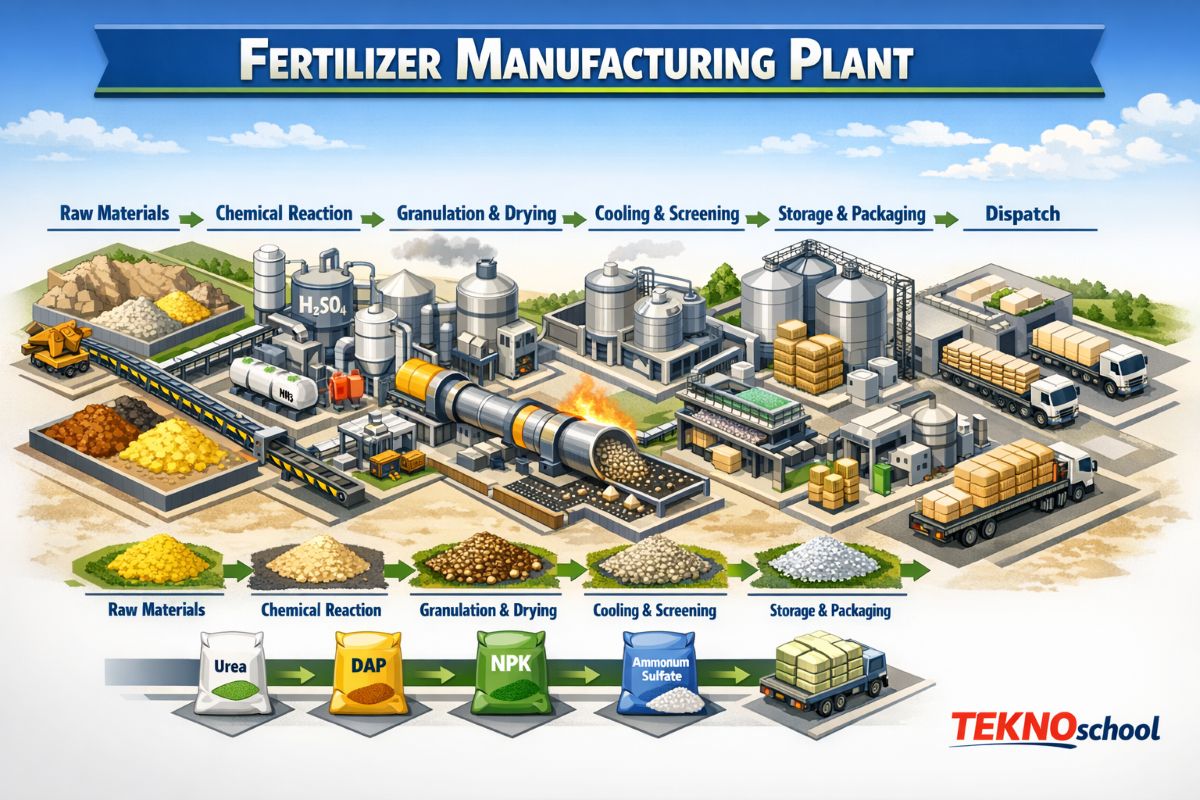
🌾 Fertilizer Manufacturing Plant – Complete Journey From Raw Materials to Final Products
Fertilizers are the backbone of modern agriculture. They replenish essential nutrients in the soil, boost crop yields, and support global food security. Behind every bag of urea, DAP, NPK, or ammonium sulfate lies a complex chemical manufacturing process involving high‑pressure reactors, reformers, compressors, granulators, and world‑class engineering.
⛽ 1. Raw Materials Used in Fertilizer Manufacturing
Fertilizer plants use a combination of natural minerals, industrial chemicals, and atmospheric nitrogen.
🔹 Primary Raw Materials
- Natural Gas (CH₄)
- Air (N₂ + O₂)
- Phosphate Rock
- Sulfur / Sulfuric Acid
- Potash (KCl)
- CO₂
- Water (DM water)
🔹 Secondary Chemicals
- Ammonia (NH₃)
- Nitric Acid (HNO₃)
- Phosphoric Acid (H₃PO₄)
- Potassium salts
- Additives & conditioners
🏭 2. Major Fertilizer Products
🌱 Nitrogenous Fertilizers
- Urea
- Ammonium Nitrate
- Ammonium Sulfate
- CAN
🌱 Phosphatic Fertilizers
- DAP
- MAP
- SSP
🌱 Potassic Fertilizers
- MOP
- SOP
🌱 Complex Fertilizers
- NPK grades (10‑26‑26, 12‑32‑16, 20‑20‑0, etc.)
🔥 3. Fertilizer Manufacturing Process – Step-by-Step
Fertilizer plants typically consist of three major production blocks:
- Ammonia Plant
- Urea / Nitric Acid / Phosphoric Acid Plant
- Granulation / Prilling / Finishing Plant
🧪 3.1 Ammonia Production (Haber–Bosch Process)
🔹 Process Steps
- Desulfurization–Sulfur compounds are removed from the feedstock to prevent catalyst poisoning in downstream units.
- Sulfur compounds are removed from natural gas using a Hydrodesulfurization (HDS) reactor and ZnO absorber, typically constructed from carbon steel with stainless‑steel internals.
- Primary Reforming-Natural gas reacts with steam over a nickel catalyst to produce hydrogen, carbon monoxide, and carbon dioxide. Natural gas reacts with steam over a nickel catalyst inside
- Primary Reforming Tubes housed in a Fired Reformer Furnace, with tubes made of high‑temperature Cr‑Ni alloys (e.g., HK40, HP‑mod).
- Secondary Reforming-Air is added to further oxidize remaining hydrocarbons and adjust the nitrogen‑to‑hydrogen ratio.
- Air is injected to complete hydrocarbon conversion in a Secondary Reformer Vessel lined with refractory bricks and equipped with high‑temperature alloy burners.
- Shift Conversion-Carbon monoxide is converted to carbon dioxide while generating additional hydrogen through the water–gas shift reaction.
- Carbon monoxide is converted to CO₂ and H₂ in High‑Temperature Shift (HTS) and Low‑Temperature Shift (LTS) Reactors, typically fabricated from alloy steel with stainless‑steel catalyst baskets.
- CO₂ Removal: Carbon dioxide is separated from the gas mixture using chemical or physical absorption systems. CO₂ is absorbed using MEA/DEA absorbers, regenerators, and wash towers, generally built from carbon steel with stainless‑steel cladding due to amine corrosion.
- Methanation-Trace carbon oxides are converted into methane to protect the ammonia synthesis catalyst. Trace CO and CO₂ are converted to methane in a Methanator Reactor containing a nickel catalyst, usually made from stainless steel (SS304/SS316) to handle clean synthesis gas.
- Ammonia Synthesis-Purified hydrogen and nitrogen react over an iron catalyst at high pressure to form ammonia. Hydrogen and nitrogen react over an iron catalyst in a High‑Pressure Ammonia Converter, constructed from thick‑wall alloy steel (e.g., 2.25Cr‑1Mo) with internal stainless‑steel liners.
🔥 Critical Parameters
- Reformer temperature: 800–900°C
- Synthesis pressure: 150–250 bar
- H₂:N₂ ratio = 3:1
🧪 3.2 Urea Production (Stamicarbon / Snamprogetti Process)
🔹 Process Steps
- Carbamate Formation-Liquid ammonia and carbon dioxide react at high pressure in a Carbamate Condenser / Reactor, typically constructed from 316L Urea‑Grade Stainless Steel to resist carbamate corrosion.
- Urea Conversion-Ammonium carbamate partially dehydrates to urea inside a High‑Pressure Urea Reactor, made from Urea‑Grade 316L SS with special passivation layers for corrosion resistance.
- Decomposition & Recycling-Unconverted carbamate is decomposed in High‑Pressure and Medium‑Pressure Decomposers/Strippers, usually fabricated from 316L UG SS or Duplex Stainless Steel, and the recovered NH₃ + CO₂ are recycled.
- Evaporation-Urea solution is concentrated in Vacuum Evaporators / Falling Film Evaporators, commonly built from SS316L or Duplex SS to handle corrosive urea melt.
- Prilling or Granulation-Concentrated molten urea is solidified into prills or granules using a Prilling Tower (carbon steel shell with internal SS components) or a Granulator (SS304/SS316 contact parts with scrubbers and coolers).
🔥 Critical Parameters
- Reactor pressure: 140–160 bar
- Reactor temperature: 180–190°C
- NH₃:CO₂ ratio: 3.2–3.5
🧪 3.3 Phosphoric Acid & DAP/NPK Production
🔹 Phosphoric Acid Process
- Phosphate rock + sulfuric acid → phosphoric acid + gypsum-Phosphate rock reacts with sulfuric acid in a Dihydrate Reactor / Attack Tank, typically constructed from rubber‑lined carbon steel or FRP to resist strong acid corrosion, producing phosphoric acid slurry and gypsum.
- Filtration-The phosphoric acid–gypsum slurry is separated in a Horizontal Belt Filter or Tilting Pan Filter, usually made from SS316L, FRP, or rubber‑lined steel, to obtain crude phosphoric acid and remove gypsum cake.
- Concentration-Crude phosphoric acid is concentrated in Vacuum Evaporators / Forced Circulation Evaporators, commonly fabricated from SS316L, Alloy‑20, or high‑silicon cast iron, to achieve the desired P₂O₅ strength.
🔹 DAP Production
- Ammonia neutralization-Ammonia reacts with phosphoric acid in a Neutralizer / Reactor Tank, typically constructed from rubber‑lined carbon steel or FRP, to form ammonium phosphate slurry under controlled temperature.
- Slurry granulation-The neutralized slurry is sprayed onto recycled fines inside a Granulator (Drum or Pipe‑Cross Granulator) made from SS316L or carbon steel with anti‑corrosive lining, forming uniform fertilizer granules.
- Drying & cooling– Wet granules are dried in a Rotary Dryer (carbon steel shell with stainless‑steel internals) and then cooled in a Rotary Cooler (carbon steel), ensuring proper hardness and moisture reduction before screening.
🧪 Short Explanation of Each Fertilizer Process
🌬️ 1. Ammonia Production (Haber–Bosch Process)
Ammonia is produced by converting natural gas into hydrogen, mixing it with nitrogen from air, and reacting both at high pressure over an iron catalyst. The key steps are reforming → shift conversion → CO₂ removal → ammonia synthesis.
🧪 2. Urea Production (NH₃ + CO₂ Process)
Urea is made by reacting ammonia with carbon dioxide to form ammonium carbamate, which then dehydrates into urea. The process includes carbamate formation → conversion → evaporation → prilling/granulation.
🧪 3. Nitric Acid Production (Ostwald Process)
Ammonia is oxidized over a platinum catalyst to form nitric oxide, which further oxidizes to nitrogen dioxide and is absorbed in water to form nitric acid. Steps: ammonia oxidation → NO to NO₂ conversion → absorption.
🧪 4. Ammonium Nitrate Production
Ammonium nitrate is produced by neutralizing nitric acid with ammonia to form a hot melt, which is then concentrated and solidified. Steps: neutralization → evaporation → prilling/granulation.
🧪 5. Phosphoric Acid Production (Wet Process)
Phosphate rock reacts with sulfuric acid to produce phosphoric acid and gypsum. Steps: rock grinding → acid reaction → filtration → concentration.
🌾 6. DAP/MAP Production (Di/Mono ammonium Phosphate)
Phosphoric acid is neutralized with ammonia to form a slurry, which is granulated and dried to produce DAP or MAP. Steps: neutralization → granulation → drying → cooling → screening.
🌱 7. SSP (Single Super Phosphate) Production
Phosphate rock is reacted with sulfuric acid to form a semi‑solid mass that cures and is later crushed. Steps: rock + acid reaction → curing → crushing → screening.
🧪 8. NPK Complex Fertilizer Production
NPK fertilizers are made by combining ammonia, phosphoric acid, potash, and fillers in a granulation drum. Steps: mixing → granulation → drying → cooling → screening → coating.
🧪 9. MOP (Muriate of Potash) Processing
Potash ore is crushed, purified by flotation or crystallization, and dried to produce MOP. Steps: crushing → separation → drying → screening.
🧪 10. SOP (Sulfate of Potash) Production
SOP is produced either by reacting potassium chloride with sulfuric acid or via salt‑lake brine processing. Steps: reaction/crystallization → separation → drying.
🔥 11. Granulation Process (Urea, DAP, NPK)
Liquid or slurry fertilizer is sprayed onto recycled fines in a rotating drum or fluidized bed to form granules. Steps: nucleation → layering → shaping → drying.
🏯 12. Prilling Process (Urea)
Molten urea is sprayed from the top of a tall tower, forming spherical prills as it cools during free fall. Steps: melting → spraying → cooling → screening.
🌪️ 13. Neutralization Processes (Ammonium Sulfate, CAN)
Acids are neutralized with ammonia to form stable salts, which are then crystallized or granulated. Steps: neutralization → concentration → solidification.
🔄 14. Steam Reforming (Hydrogen Production)
Natural gas reacts with steam over a catalyst to produce hydrogen and CO. Steps: desulfurization → reforming → shift conversion.
♻️ 15. CO₂ Recovery & Compression
CO₂ from reforming is purified and compressed for urea synthesis. Steps: absorption → stripping → compression.
🧊 16. Cooling & Finishing
Granules or prills are cooled, coated, and stored. Steps: cooling → coating → conveying → storage.
⚙️ 4. Mechanical Equipment Used in Fertilizer Plants
Mechanical equipment keeps the plant running — compressing gases, pumping liquids, generating steam, and handling solids.
🔧 Rotary Equipment
🌀 Centrifugal Compressors – (Ammonia Synthesis Loop)
How it works:
A high‑speed impeller accelerates gas, and diffusers convert velocity into pressure.
Where used:
- Compressing the H₂ + N₂ mixture to 150–250 bar in the ammonia loop
- CO₂ compression in urea plants
example:
Four-stage centrifugal compressor for synthesis gas.
🔩 Reciprocating Compressors – (CO₂ Compression in Urea Plants)
How it works:
A piston compresses gas inside a cylinder.
Where used:
- CO₂ compression to 140–160 bar
- Ammonia refrigeration
example:
Urea plants use 2–3 stage reciprocating compressors for CO₂ feed.
💨 Steam Turbines – (Driving Compressors & Pumps)
How it works:
High‑pressure steam rotates turbine blades.
Where used:
- Drives syngas compressors
- Drives boiler feedwater pumps
example:
IFFCO Kalol uses turbine‑driven compressors for reliability.
💧 Pumps – (Throughout the Plant)
How they work:
Centrifugal pumps impart velocity; reciprocating pumps deliver high pressure.
Where used:
- Boiler feedwater
- Ammonia transfer
- Acid circulation
example:
Phosphoric acid plants use rubber‑lined slurry pumps for abrasive rock slurry.
🌬️ Cooling Tower Fans – (Cooling Water System)
How they work:
Axial fans force air through water to remove heat via evaporation.
Where used:
- Cooling Towers
example:
RCF Trombay uses induced‑draft cooling towers for heat rejection.
⚗️ 5. Process Equipment Used
Process equipment performs chemical reactions, heat transfer, separation, and product formation.
🧪 5.1 Ammonia Plant Equipment
🔥 Primary Reformer – (Heart of Ammonia Plant)
How it works:
Natural gas + steam pass through catalyst tubes heated to 800–900°C.
Where used:
- First step of ammonia production
example:
Chambal Fertilizers uses top‑fired reformers with 250+ tubes.
🔥 Secondary Reformer – (Adds Nitrogen)
How it works:
Air is injected; partial combustion raises the temperature to ~1000°C.
Where used:
- Balances H₂:N₂ ratio
example:
KRIBHCO uses side‑fired secondary reformers.
♻️ Shift Converters – (CO → CO₂ Conversion)
How it works:
CO reacts with steam over the Fe/Cr catalyst.
Where used:
- Produces hydrogen
example:
Most Indian plants use HTS + LTS converters.
🧴 CO₂ Absorber – (Amine System)
How it works:
MEA/MDEA solvent absorbs CO₂.
Where used:
- CO₂ removal
example:
IFFCO uses Benfield/MDEA systems.
⚗️ Ammonia Converter – (Haber–Bosch Reactor)
How it works:
H₂ + N₂ react over an iron catalyst at 150–250 bar.
Where used:
- Final ammonia production
example:
RCF Trombay uses axial‑radial converters.
🧪 5.2 Urea Plant Equipment
🧪 High‑Pressure Urea Reactor
How it works:
NH₃ + CO₂ → ammonium carbamate → urea.
Where used:
- Core of urea synthesis
example:
Snamprogetti plants use a pool condenser + reactor.
🧪 Carbamate Condenser
How it works:
Unreacted NH₃ + CO₂ condense to carbamate.
Where used:
- Energy‑saving loop
Real example:
Stamicarbon uses falling‑film condensers.
🧪 HP/MP Strippers
How they work:
Heat + pressure separate unreacted gases.
Where used:
- Urea purification
example:
Chambal Gadepan HP stripper operates at 140–150 bar.
🏯 Prilling Tower / Granulator
How it works:
- Prilling: molten urea falls from the tower top
- Granulation: fluidized bed forms strong granules
Where used:
- Final product formation
example:
IFFCO uses granulation for dust‑free urea.
🧪 5.3 Phosphatic Fertilizer Equipment
🧪 Acid Reactors
How they work:
Phosphate rock reacts with sulfuric acid.
Where used:
- DAP, SSP, NPK
example:
RCF Trombay uses continuous stirred reactors.
🔄 Granulation Drum
How it works:
Slurry + recycled fines tumble to form granules.
Where used:
- DAP/NPK granulation
example:
Coromandel uses rotary drum granulators.
🔥 Fluidized Bed Dryer
How it works:
Hot air fluidizes granules, removing moisture.
Where used:
- Drying DAP/NPK
example:
Most Indian NPK plants use FBD dryers.
🌪️ Scrubbers & Cyclones
How they work:
- Cyclones remove dust
- Scrubbers absorb acidic gases
Where used:
- Pollution control
example:
DAP plants use venturi scrubbers for ammonia fumes.
🛠️ 6. Maintenance in Fertilizer Plants
🔧 Key Activities
- Reformer tube inspection
- Compressor overhauling
- Catalyst replacement
- Heat exchanger cleaning
- Pipeline thickness measurement
- Vibration analysis
🔧 Examples
- Performs reformer tube IR scanning every shutdown
- Overhauls syngas compressors every 2 years
⚠️ 7. Safety in Fertilizer Plants
🚨 Major Hazards
- Ammonia leakage
- Hydrogen explosion
- Acid burns
- High‑pressure failures
🛡️ Safety Measures
- Gas detectors
- ESD systems
- PPE
- Permit‑to‑work
- HAZOP
8. India’s Top 5 Fertilizer Plants
🏭 1. IFFCO – Kalol & Kandla (Gujarat)
Products: Urea, NPK
Capacity: 2+ million MT/year
🏭 2. KRIBHCO – Hazira (Gujarat)
Products: Ammonia, Urea
Capacity: 2.2 million MT/year
🏭 3. NFL – Panipat & Bathinda
Products: Urea
Capacity: 1.4 million MT/year
🏭 4. RCF – Trombay (Mumbai)
Products: Urea, NPK, industrial chemicals
🏭 5. Chambal Fertilizers – Gadepan (Rajasthan)
Products: Urea
Capacity: @3.4 million MT/year
Final Thoughts
Fertilizer plants are engineering marvels combining chemistry, thermodynamics, high‑pressure systems, and precision control. From natural gas reforming to urea granulation and NPK blending, every step requires advanced technology, skilled manpower, and strict safety standards.
India’s fertilizer industry continues to grow with modern plants, energy‑efficient technologies, and world‑class engineering practices — ensuring food security for millions.