Dynamic Stability and Power Modulation in HVDC Systems
Dynamic Stability and Power Modulation in HVDC Systems
Dynamic Stability-How HVDC transmission actively shapes system dynamics — damping oscillations, stabilising voltage, and coordinating multi-terminal grids through precise power modulation strategies.
Introduction: Dynamic Stability in AC/DC Systems
When HVDC links are embedded within large AC power systems, their interaction with the surrounding network goes far beyond simple power transfer. The DC link becomes an active participant in system dynamics — capable of either aggravating or resolving the oscillatory and voltage stability challenges that characterise modern interconnected grids.
Dynamic stability refers to the ability of a power system to maintain synchronism and acceptable voltage levels following disturbances — ranging from minor load fluctuations to major contingency events like line faults or generator trips. In classical AC systems, this stability is shaped by synchronising torques, damping torques, and the network’s reactive power capacity. HVDC converters, operating through fast thyristor or IGBT switching, introduce a uniquely controllable power flow element into this dynamic environment.
The fundamental advantage of HVDC in stability terms is response speed. While conventional AC system controls — governor action, AVR response, PSS output — operate over timescales of hundreds of milliseconds to seconds, HVDC power order changes can be executed within 10 to 50 milliseconds. This speed advantage is the cornerstone of HVDC power modulation as a stabilising tool.
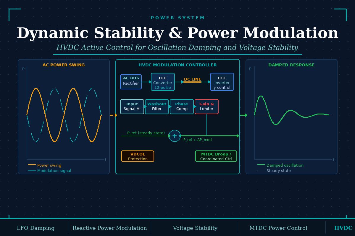
HVDC power modulation superimposes a dynamic correction signal onto the steady-state DC power order, causing the converter to inject or absorb active power in a controlled pattern that counteracts power system oscillations. The modulation signal is derived from measurements of AC system quantities — frequency, voltage, or current — and processed through controllers tuned to the target oscillatory mode.
Power Modulation for Damping Low-Frequency Oscillations
Low-frequency oscillations (LFOs) are a persistent challenge in large AC networks. They arise from interactions between generator rotors and manifest at frequencies typically between 0.1 Hz and 2.0 Hz. Inter-area oscillations — where groups of generators in one region swing against groups in another — are particularly problematic, often involving frequencies of 0.2 to 0.8 Hz and exhibiting very low natural damping.
HVDC power modulation addresses this through a modulation controller that continuously monitors a stabilising signal derived from the AC system, computes a corrective power increment, and adjusts the DC power reference in real time. The process mirrors the function of a Power System Stabiliser (PSS) on a generator’s AVR, but operates through the DC link rather than through field excitation.
The input signal to the modulation controller must be sensitive to the target oscillatory mode and available at the measurement point. Commonly used signals include:
Frequency deviation (delta-f): Measured at the inverter or rectifier AC bus. Directly reflects rotor speed deviations of nearby generators.
Accelerating power: Derived from generator shaft measurements. Highly sensitive to inter-area modes but requires access to generator data.
AC current or line power flow: Available from tie-line measurements. Useful for inter-area modes where the oscillation is observable in the power interchange.
The modulation controller follows a standard signal processing chain:
Washout filter: High-pass filter that removes steady-state components from the input signal, ensuring the modulation acts only on oscillatory transients.
Phase compensation: Lead-lag stages that advance the phase of the modulation signal so the resulting power change is in phase with the damping torque required on the oscillating generators.
Gain and limiter: A tunable gain amplifies the signal, with hard limiters preventing the modulation from driving the DC link outside safe operating bounds.
The modulation output (delta-P_mod) is added to the normal DC power order (P_ref), giving an effective power reference of P_ref + delta-P_mod. When an oscillation causes sending-end generators to accelerate, the modulation controller increases DC power transfer — absorbing excess mechanical energy. When those generators decelerate in the next half-cycle, DC power is reduced, releasing energy back into the AC system. This cyclic action provides positive damping torque at the oscillation frequency.
Practical Considerations in Power Modulation
Deploying power modulation in a real HVDC system involves engineering trade-offs that go beyond the theoretical controller design.
Modulation depth is constrained by the minimum DC current requirement of the converter. LCC-HVDC thyristor converters require a minimum extinction angle (gamma_min) and a minimum direct current to maintain stable commutation. Power modulation that drives the DC current below this threshold risks commutation failure — a serious fault condition that can temporarily block the converter.
Commutation failure risk during modulation: Aggressive power reduction commands at the inverter reduce DC current rapidly. If AC voltage dips simultaneously — which is common during the disturbances that trigger modulation — the reduced current and lower commutation voltage combine to push the extinction angle below gamma_min. This is why modulation limiters must account for AC voltage conditions, not just DC current magnitude.
Interaction between modulation and normal control: HVDC converters already operate under constant current control (CC) and constant extinction angle control (CEA). The modulation signal must be coordinated with these inner loops. Typically, modulation acts as an outer loop that adjusts the power reference, while inner current and angle controllers remain active to protect the converter. Poor coordination between modulation dynamics and inner loop bandwidths can produce controller fighting — where the inner loop partially cancels the intended modulation effect.
Multiple mode targeting: A single modulation controller tuned to one inter-area mode may produce adverse interactions with other oscillatory modes in the system. Wide-area measurement systems (WAMS) and adaptive tuning algorithms are increasingly used to adjust modulation controller parameters in real time as operating conditions shift.
Modulation limiters must be coordinated with both the maximum and minimum DC power ratings of the HVDC link, and must respect the DC voltage operating range. Pushing the DC link into inverter operation from rectifier mode — or vice versa — while AC disturbances are present can trigger cascading failures across both ends of the system.
Extinction Angle and Reactive Power Modulation
Active power modulation is only one dimension of HVDC’s dynamic control capability. The extinction angle gamma at the inverter, and the firing angle alpha at the rectifier, both determine the reactive power drawn from the AC system. Modulating these angles provides a reactive power control lever that complements active power modulation.
In normal steady-state operation, the inverter is controlled to maintain gamma at a value slightly above gamma_min — typically 15 to 18 degrees — to provide a safety margin against commutation failure. Increasing gamma above this value causes the inverter to draw more reactive power from the AC network, which raises the AC voltage at the inverter bus. Decreasing gamma toward gamma_min reduces reactive consumption and can support AC voltage recovery following a voltage dip.
For VSC-HVDC systems, reactive power modulation is considerably more flexible. VSC converters can independently control active and reactive power at each terminal, operating at any point within the converter’s power capability circle. This means VSC-HVDC can simultaneously provide active power modulation for damping while injecting or absorbing reactive power for voltage support — two functions that are coupled and constrained in LCC systems.
VSC-HVDC reactive power modulation can be deployed even when DC power transfer is zero — for example, when the DC link is in standby mode. This makes VSC stations valuable as dynamic reactive power compensators (STATCOM mode), contributing to system stability without consuming DC transmission capacity.
Power Modulation in Multi-Terminal DC (MTDC) Systems
Multi-terminal HVDC (MTDC) systems introduce additional complexity and additional capability for dynamic stability control. With three or more converter terminals interconnected through a common DC network, power modulation must account for the distribution of power changes across multiple AC systems simultaneously.
In a point-to-point HVDC link, a modulation-driven power increase at the rectifier is matched by an equal power increase at the inverter — the relationship is one-to-one. In an MTDC system, a change in power at one terminal must be shared among the remaining terminals according to a droop or master-slave control scheme. The distribution of this corrective power among multiple AC subsystems is itself a design variable that can be optimised for maximum damping benefit across the entire interconnected system.
A central controller receives wide-area measurements from all AC subsystems and computes optimal modulation signals for each terminal. High damping performance, but requires reliable communication infrastructure and has a single-point failure risk.
Each terminal applies a local frequency or power droop characteristic. Modulation arises naturally from local AC system measurements. No communication required between terminals — more robust but less optimal in damping allocation.
Local droop controllers handle fast primary response; a supervisory layer using low-bandwidth communication refines the power distribution for optimal damping. Combines robustness with performance.
A particular challenge in MTDC power modulation is DC voltage regulation during transient events. When one terminal rapidly reduces power output — for active modulation or following a fault — the DC bus voltage rises transiently because power injected by other terminals exceeds the suddenly reduced offtake. The DC voltage controller at each terminal must respond quickly to redistribute power, but its response time must be coordinated with the AC-side modulation dynamics to avoid creating oscillations on the DC bus itself.
Voltage Stability in AC/DC Systems
Voltage stability — the ability of the system to maintain acceptable voltages at all buses following disturbances — is profoundly influenced by the presence of HVDC converters. LCC converters are significant consumers of reactive power, absorbing 50 to 60 per cent of the DC power transferred as reactive demand from the AC system. This reactive load is not fixed; it varies with DC current, firing angle, and AC voltage — creating a non-linear coupling between the DC power flow and AC voltage that complicates stability analysis.
The critical voltage stability concern in LCC-HVDC systems is the risk of voltage instability near the inverter bus. Because the inverter’s reactive power consumption increases as AC voltage falls — due to the need to maintain gamma above gamma_min — a voltage drop at the inverter bus tends to cause additional reactive demand from the converter, further depressing the voltage. This positive feedback mechanism can lead to voltage collapse if the AC system lacks sufficient reactive power reserves or if the short-circuit ratio (SCR) at the inverter bus is low.
The Short Circuit Ratio (SCR) at the inverter bus quantifies the strength of the AC network relative to the DC power rating: SCR equals Short Circuit MVA divided by DC Power in MW. Systems with SCR below 2 are classified as weak AC systems, where voltage interaction with the LCC converter is severe. Effective Infeed SCR (ESCR) accounts for reactive compensation already installed, giving a more accurate measure of the dynamic coupling. Low-ESCR systems demand careful coordination of reactive compensation, modulation, and VDCOL characteristics.
Voltage Dependent Current Order Limiter (VDCOL) is a standard HVDC protective function directly relevant to voltage stability. When AC voltage at the inverter drops significantly — indicating stress on the AC system — VDCOL automatically reduces the DC current order. This reduces both active and reactive power demand from the LCC converter, allowing the AC system to recover voltage rather than collapsing under the converter’s continued reactive demand. VDCOL is a protective measure, not an optimising control, but its interaction with power modulation must be carefully managed.
VSC-HVDC fundamentally improves the voltage stability picture because it can supply reactive power to the AC system rather than consuming it. A VSC inverter terminal can act as a reactive power source during voltage depression events, counteracting the destabilising reactive deficit that plagues LCC systems in weak AC networks.
Integrated Dynamic Modelling of AC/DC Systems
Analysing the combined dynamic behaviour of AC/DC systems requires integrated simulation models that correctly represent both the fast DC-side dynamics and the slower AC-side electromechanical dynamics simultaneously. The time-scale separation between these phenomena creates challenges for both model formulation and numerical integration.
DC-side dynamics — including commutation transients, DC line travelling waves, and converter switching — operate at timescales of microseconds to milliseconds. AC electromechanical dynamics — rotor angle swings, governor response, AGC action — operate over hundreds of milliseconds to tens of seconds. Including both in a single time-domain simulation would require extremely small integration time steps, making simulations computationally prohibitive for large systems.
For power modulation controller design, the small-signal linearised model is the primary tool. The AC network, synchronous generators, their controls (AVR, PSS, governor), load characteristics, and the HVDC converter average model are all linearised around a chosen operating point and assembled into a state-space representation. Eigenvalue analysis of this combined model identifies the oscillatory modes present in the system — their frequencies, damping ratios, and participation factors. The modulation controller is then designed so that its closed-loop effect shifts the target eigenvalue into a region of adequate damping.
For MTDC systems, the integrated small-signal model must include the DC network dynamics — the inductance and capacitance of the DC cables or overhead lines, plus the DC voltage controller dynamics at each terminal — in addition to all AC subsystem models. This substantially increases model order and requires careful model order reduction techniques before controller design is tractable.
Time-domain validation using the full nonlinear model — typically in EMT software for converter accuracy, or in transient stability programs for large-scale AC system representation — is essential to confirm that the modulation controller behaviour predicted by the linearised design holds across the range of operating conditions the system will actually experience. The integrated dynamic model thus serves both the design phase and the validation phase of HVDC stability controller development, forming the technical foundation on which the entire power modulation strategy rests.
Key Takeaways
Superimposes corrective power signals on the DC reference, providing positive damping torque at inter-area oscillation frequencies through sub-100ms response.
Extinction angle control provides a reactive power lever complementing active modulation; VSC systems offer independent Q-control without commutation constraints.
Power changes distribute across multiple AC subsystems; droop, centralised, or hierarchical control strategies balance damping performance against communication reliability.
Small-signal linearised models drive controller design; EMT or hybrid time-domain simulation validates behaviour across the full nonlinear operating range.