
AC vs. DC Transmission
Power System
AC vs. DC Transmission:
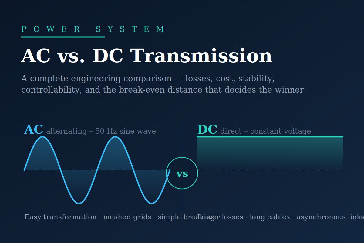
AC vs. DC Transmission-Two ways of moving electrical energy, two very different sets of strengths — and clear rules for when each one wins.
Start With the Physics
The fundamental difference between AC and DC transmission is not the conductor, the tower, or the insulator — it is what the electric and magnetic fields are doing. In an AC line, voltage and current reverse direction 50 or 100 times per second. Every reversal charges and discharges the line’s capacitance and builds and collapses the magnetic field around its inductance. These effects consume reactive power, limit how far energy can travel, and force every connected generator to spin in exact synchronism. A DC line has none of this: fields are established once and stay put. Steady fields mean no reactive power demand, no charging current, no stability angle between the two ends — only resistance matters.
AC also uses its conductors less efficiently. Alternating current crowds toward the conductor surface (skin effect), raising effective resistance. And because AC voltage swings up to a peak value √2 times its RMS value, insulation must be rated for the peak, while power transfer is governed by the RMS. A DC line stressed to the same insulation level carries its full rated voltage continuously — roughly 40% more usable voltage from the same air gap and insulator string.
Foundational Concept
A bipolar DC line delivers comparable power with two conductors instead of three, no skin effect, no reactive power flow, and full utilisation of insulation. Per kilometre of route, DC transmission is inherently cheaper. What makes AC dominant is what sits at the end of the line — the transformer.
Why AC Still Rules the Grid
AC’s decisive advantage is voltage transformation. A transformer changes AC voltage levels with efficiency above 99%, has no moving parts, and has modest cost. This makes the entire layered architecture of the grid possible — generate at medium voltage, transmit at extra-high voltage, distribute at low voltage. DC has no equivalent passive device: changing DC voltage requires power-electronic converters, and connecting a DC line to the AC world requires a converter station at each end costing many times more than an equivalent AC substation. Circuit breaking is also far easier in AC, because current naturally passes through zero every half-cycle, giving the breaker a moment to extinguish the arc. Interrupting large DC currents demands specialised — and expensive — HVDC breakers.
The result is the classic economic picture: DC has high terminal cost but low per-kilometre cost; AC has low terminal cost but higher per-kilometre cost plus compensation requirements as length grows. Plotting total cost against distance, the two lines cross at the break-even distance — typically around 500–800 km for overhead lines, but only 40–80 km for cables, where AC charging current becomes crippling.
Side-by-Side Comparison
| Aspect | AC Transmission | DC Transmission |
|---|---|---|
| Voltage transformation | Simple, cheap, >99% efficient (transformer) | Requires costly converter stations |
| Conductors per circuit | Three (plus earth wire) | Two (bipolar), narrower right-of-way |
| Line losses | Higher — skin effect, reactive current, corona | Lower — full conductor use, no reactive flow |
| Cable transmission | Limited to ~40–80 km by charging current | Practically unlimited length |
| Stability constraint | Synchronism must be maintained; angle limits transfer | No stability limit; links asynchronous grids |
| Power flow control | Follows network impedance; needs FACTS to steer | Fully and rapidly controllable by converters |
| Circuit breaking | Easy — natural current zeros | Difficult — needs special HVDC breakers |
| Terminal cost | Low (substation + transformers) | High (converter stations, filters) |
| Break-even distance | Preferred below ~500–800 km overhead | Preferred beyond break-even, or any long cable |
Design Constraint
HVDC converters based on line-commutated thyristor technology consume reactive power (roughly 50–60% of the DC power rating) and inject harmonics, requiring large filter banks and reactive compensation at each terminal. Modern voltage-source converters (VSCs) remove these limitations at the cost of somewhat higher losses per converter.
Where Each Technology Wins
AC remains unbeatable for the networked grid itself — the meshed web of lines, substations, and transformers where power must be tapped, transformed, and protected at thousands of points. DC excels in four specific missions: very long overhead corridors delivering bulk power point-to-point (India’s ±800 kV multi-gigawatt links are prime examples), submarine and underground cable connections, asynchronous interconnections between grids operating at different frequencies or with independent frequency control, and precisely controlled power exchange where the fast, exact controllability of converters is itself the product.
Key Insight
AC and DC are not competitors — they are complementary layers. Modern grids embed HVDC links inside AC networks, using DC for bulk haulage and controllability while AC handles collection, distribution, and transformation. The engineering question is never “AC or DC?” in general, but “AC or DC for this corridor, this distance, this duty?”
Bringing It Together
The AC–DC comparison ultimately reduces to a trade between the line and the terminal. DC offers the superior line: fewer conductors, lower losses, full insulation utilisation, no stability limit, and unlimited cable length. AC offers the superior terminal: effortless voltage transformation, simple protection, and a century of mature, inexpensive equipment. Below the break-even distance, the terminals dominate the economics and AC wins; beyond it, or wherever cables and asynchronous connection are involved, the line dominates, and DC wins. As converter costs fall and grids demand ever more controllability for renewable integration, that break-even point keeps shifting — and the modern power system is increasingly a deliberate hybrid of both.





