Reactive Power and Voltage Control
Reactive Power and Voltage Control in Power Systems
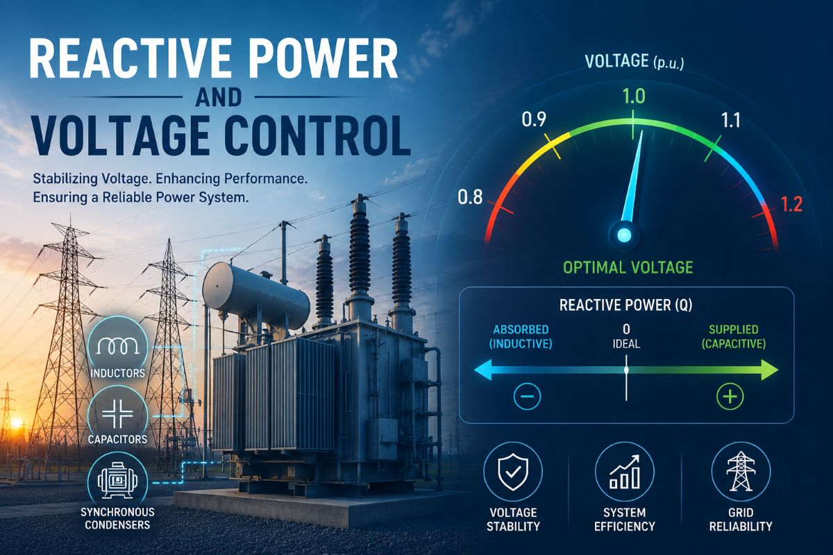
If frequency tells us whether the system has enough real power, voltage tells us whether it has enough reactive power. The two quantities are tied together because the flow of reactive power through the inductance of lines and transformers causes voltage to drop along the way. Keep reactive power in balance and voltages stay close to their rated values; let it run short, and voltages sag; let it run in surplus, and voltages climb. Holding voltage within a narrow band at every busbar is, therefore, at heart, the job of managing reactive power.
Reactive power does not perform useful work in the way real power does; it oscillates back and forth between the magnetic and electric fields of the system. Yet it is essential — every transformer and induction motor needs reactive power to magnetise its core, and the network itself consumes or supplies reactive power depending on how heavily it is loaded. Because reactive power does not travel well over long distances without dragging voltage down with it, it must be balanced locally, close to where it is needed.
Real power and frequency form the P–f control loop; reactive power and voltage form the Q–V control loop. The two are nearly independent, which is why voltage control can be studied as the management of reactive power flow.
Production and Absorption of Reactive Power
Reactive power is produced by capacitive elements and absorbed by inductive ones. Synchronous generators are the most flexible source: by adjusting their field excitation, they can either generate reactive power (over-excited) or absorb it (under-excited), which makes them the primary regulators of voltage at the points where they connect. Shunt capacitors and the natural capacitance of overhead lines and cables also produce reactive power.
On the absorbing side stand the inductive loads — induction motors above all — together with transformers, shunt reactors, and transmission lines when they are heavily loaded. A transmission line is a special case worth understanding: it has both series inductance, which absorbs reactive power in proportion to the square of the current it carries, and shunt capacitance, which produces reactive power in proportion to the square of its voltage. At light load, the capacitance dominates, and the line is a net source; at heavy load, the inductance dominates, and the line is a net sink. The crossover happens at a loading called the surge impedance loading, where a line neither produces nor absorbs reactive power overall.
Methods of Voltage Control
Because voltage depends on local reactive balance, it cannot be controlled from a single central point the way frequency is. Instead, it is managed by a family of devices spread across the network. The main methods are: adjusting the excitation of generators to vary the reactive power they supply; using tap-changing transformers to shift the voltage ratio between windings; and installing reactive compensation — shunt reactors, shunt capacitors, series capacitors, and synchronous condensers — at strategic points to add or remove reactive power where the network needs it.
Generators handle the moment-to-moment regulation through their automatic voltage regulators. Tap-changers, which can operate under load, trim the voltage profile across transformation stages. The compensation devices that follow are the tools that directly inject or absorb reactive power, and each has a distinct character.
Shunt Reactor
A shunt reactor is an inductive coil connected from line to neutral that absorbs reactive power and so pulls voltage down. Its main purpose is to counter the reactive power produced by long, lightly loaded transmission lines and underground cables. When such a line carries little current, its shunt capacitance dominates, and the receiving-end voltage can rise above the sending-end value — the well-known Ferranti effect. A shunt reactor soaks up the excess capacitive reactive power and holds the voltage down to a safe level.
Shunt reactors are therefore most valuable on extra-high-voltage networks and during off-peak periods. They may be permanently connected or switched in only when the load is light and switched out as the load builds up and the line begins absorbing reactive power on its own.
Shunt Capacitor
A shunt capacitor does the opposite: connected from line to neutral, it produces reactive power and so raises voltage. It is the most common and economical means of voltage support on distribution and sub-transmission systems, where inductive load is heavy, and voltages tend to sag, especially at peak demand.
By supplying reactive power locally, a shunt capacitor relieves the upstream network of carrying that reactive current, which improves the power factor, reduces line losses, and frees up capacity in lines and transformers.
A shunt capacitor has one important limitation: the reactive power it produces falls with the square of the voltage. So just when the voltage drops, and support is most needed, the capacitor delivers less. This makes capacitors excellent for steady, predictable support but weaker at propping up a voltage that is already collapsing. They are usually arranged in switchable banks so that capacity can be matched to the daily load cycle.
Series Capacitor
A series capacitor is connected in line with the conductor rather than across it, and it works on a different principle. Its capacitive reactance partly cancels the inductive reactance of the transmission line, in effect making the line electrically shorter. Reducing the net series reactance lowers the voltage drop along the line and raises the amount of power the line can transfer between its ends.
A useful feature of the series capacitor is that its compensating effect grows automatically with load: the more current the line carries, the more voltage the series capacitor develops to oppose the line’s inductive drop. This makes it self-regulating in a way that the shunt capacitor is not. Series capacitors are mainly applied on long, heavily loaded transmission lines to improve voltage regulation and to increase the stability limit of power transfer, though they require careful protection against fault currents and the risk of resonance with system inductance.
Synchronous Condenser
A synchronous condenser is a synchronous motor running with no mechanical load on its shaft, connected to the system purely to exchange reactive power. By varying its field excitation, it can be made to produce reactive power when over-excited or absorb it when under-excited, giving it a smooth, continuously adjustable output across both directions.
This two-way, stepless capability is its great advantage over capacitor and reactor banks, which can only be switched in discrete steps and act in one direction. A synchronous condenser also contributes valuable short-circuit strength and inertia to the grid, helping support voltage during disturbances. Its drawbacks are the higher cost, the moving parts, and the maintenance of a rotating machine, which is why static devices have replaced it in many roles. It still has a place where dynamic, bidirectional voltage support and system strength are needed together.
Seen as a whole, voltage control is the art of placing the right reactive resource at the right point. Generator excitation and tap-changers provide the continuous regulation; shunt reactors absorb surplus reactive power on lightly loaded lines; shunt capacitors inject it where inductive load is heavy; series capacitors shorten long lines electrically to ease transfer; and synchronous condensers offer smooth, two-way support where the system demands it. Together, they keep the voltage profile flat and the reactive balance healthy across the entire network.