Active Power and Frequency Control
Active Power and Frequency Control in Power Systems
A power system delivers electrical energy at the same instant it is consumed; there is no large storage tank sitting between the generators and the load. Every lamp switched on, and every motor started must be matched, within a fraction of a second, by an equal increase in the power produced by the turbines spinning in the power stations. The physical link that makes this matching possible — and that signals when it fails — is the system frequency.
Each turbine-generator stores kinetic energy in its rotating mass. When the load suddenly exceeds the generation, the extra energy can only come from this spinning mass, so the rotors slow down and the frequency falls. When generation exceeds load, the surplus accelerates the rotors and frequency rises. Because all machines in an interconnected grid are electrically locked together, they share a single common frequency, making it a precise, system-wide measure of the active-power balance.
Frequency remains constant only when the generated active power equals the load plus losses at every instant. Controlling active power and controlling frequency are two views of one problem, which is why the whole real-power control scheme is built around frequency as its master signal.
Fundamentals of Speed Governing and Load Frequency Control
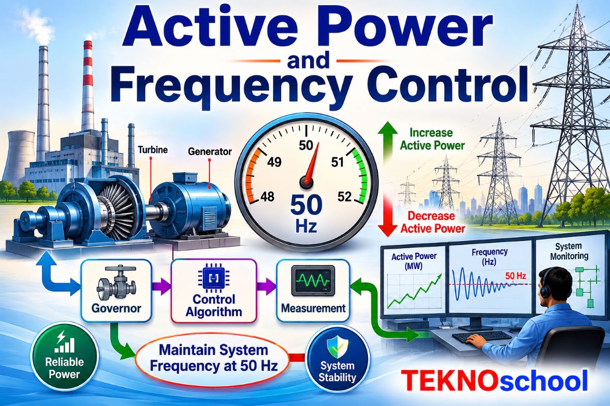
In a generating unit, active power and reactive power are controlled through two largely separate loops. The real power and frequency are handled by the load frequency control (LFC) loop, sometimes called the P–f loop, while the reactive power and voltage are handled by the automatic voltage regulator in the Q–V loop. These two are nearly independent because real power is tied strongly to rotor angle and speed, whereas reactive power is tied to voltage magnitude. The discussion of frequency control is therefore the study of the LFC loop.
At the heart of the LFC loop sits the speed governor. Its task is to sense any change in shaft speed and adjust the prime mover input — the steam valve, the water gate, or the fuel flow — to oppose that change. The simplest form, the isochronous governor, keeps speed at exactly one value by continuing to act until the error is zero. This works for a single machine supplying an isolated load, but two isochronous governors connected to the same grid would compete endlessly, each demanding its own precise frequency, and neither would settle.
The practical solution is the droop governor, which allows frequency to fall slightly as the unit takes on more load. The slope of this characteristic is the speed regulation or droop, defined as the per-unit change in frequency divided by the per-unit change in output power. A typical droop of 5% means that a 5% drop in frequency moves the unit from no load all the way to full load. This deliberate sag is what lets many machines share a load change automatically: when frequency dips, every governor on the system responds in proportion to the stiffness of its own droop line, with no central command needed. This automatic, immediate reaction is called primary control, and it forms the first and fastest layer of load frequency control.
Control of Generating Unit Power Output
A droop line fixes the relationship between frequency and output, but the operator still needs to choose how much power the unit should produce at the rated frequency. This is achieved with the speed-changer or load reference setting, which shifts the entire droop characteristic up or down without altering its slope. Raising the reference parallel-shifts the line upward so the unit carries more load at the same frequency; lowering it does the reverse.
This gives a clean two-layer arrangement. The droop provides an instantaneous, self-acting response to any frequency excursion, while the load reference provides the slower, deliberate scheduling of each unit’s contribution. A control centre can therefore set the operating point of every machine in the system while still leaving each one free to react on its own to sudden disturbances.
Composite Regulating Characteristic of the Power System
When every generator and every frequency-sensitive load is combined, the system as a whole presents a single composite regulating characteristic. Two effects add together. First, the generators collectively stiffen the system through their parallel droop responses, so the more units that are governing, the smaller the frequency change for a given disturbance. Second, a large share of the load — induction motors, fans, pumps — naturally draws less power as frequency falls, an effect captured by the load damping constant, usually expressed as a percentage change in load per percentage change in frequency.
The composite characteristic, often quoted as the system stiffness in megawatts per hertz, tells operators how far frequency will move for a given sudden loss of generation or load. A stiffer system holds frequency more tightly after a disturbance.
This combined figure governs the initial frequency dip after an event such as the tripping of a large generator. The pooled governing action and load damping arrest the fall within a few seconds and bring the system to rest at a new steady-state frequency, slightly below nominal. That residual offset is exactly what the next control layer is designed to remove.
Response Rates of Turbine Governing Systems
How quickly a unit can actually deliver its share depends on the physics of its prime mover. A hydro turbine reacts within a second or two but suffers an initial reverse “water-hammer” effect as the gates move — output briefly dips before it rises — so its governor gain must be limited. A steam turbine responds more smoothly but is paced by the boiler’s ability to hold pressure and by the time constants of its reheat stages, giving response times from several seconds to tens of seconds. Gas turbines sit between the two, ramping fuel quickly but constrained by thermal stress on hot components.
These differing rates matter because frequency support relies on very fast reserves in the opening seconds and slower reserves thereafter. Grid codes accordingly specify how rapidly a unit must raise output following a frequency drop, so that the combined response of the whole fleet keeps pace with the speed at which disturbances actually unfold.
Fundamentals of Automatic Generation Control
Primary governing arrests a frequency deviation but always leaves a steady-state offset, and in an interconnected system, it does nothing to control how power flows over the tie-lines linking neighbouring areas. Automatic Generation Control (AGC) is the secondary, slower layer that removes the offset and restores scheduled interchange. Its central quantity is the Area Control Error (ACE), which combines the tie-line power deviation with the frequency deviation multiplied by a frequency-bias factor.
By driving ACE steadily to zero, AGC accomplishes two things at once: it returns frequency to its scheduled value, and it ensures each control area absorbs its own load changes instead of leaning on its neighbours. This property is known as non-interactive control — a disturbance arising in one area is corrected by that area alone, while the rest of the interconnection returns to its original schedule.
Implementation of AGC and Economic Dispatch Control
In practice, AGC runs as a closed loop inside the energy control centre. Tie-line flows and frequency are telemetered every few seconds, the ACE is computed and filtered, and the result passes through an integrating controller that issues raise and lower signals to the regulating units until the error settles at zero.
Restoring frequency, however, is only half the objective; the generation must also be produced as cheaply as possible. This is the role of economic dispatch control (EDC). Every thermal unit has an incremental fuel cost — the cost of producing one more megawatt — that rises with output. Total fuel cost is minimised when all units in service operate at the same incremental cost, the well-known equal-incremental-cost or “equal-lambda” principle, adjusted for transmission losses. Economic dispatch solves for this optimum every few minutes and produces the most cost-effective base point for each machine.
AGC distributes its raise/lower commands among units using participation factors derived from economic dispatch, so the cheapest available capacity is moved first. EDC sets the efficient base points; AGC nudges units around them to hold frequency and interchange.
The complete scheme therefore works across three timescales at once: governing acts instantly in the first seconds, AGC corrects frequency and tie-line error over the following seconds to minutes, and economic dispatch control re-optimises the cost-efficient allocation every few minutes, feeding fresh base points back into the AGC loop.
Under-Frequency Load Shedding
When a disturbance is so severe that governing and AGC cannot arrest the frequency fall — typically after the sudden loss of a very large generator or the unplanned islanding of part of the grid — the final line of defence is under-frequency load shedding. Frequency relays automatically disconnect blocks of load in stages as frequency crosses lower thresholds successively.
By deliberately sacrificing some load, the scheme restores the generation–demand balance before frequency reaches the level at which generators would trip on their own protection — an outcome that would otherwise cascade into a complete blackout.
Shedding is arranged so that the most expendable load is dropped first while critical supplies are preserved as long as possible. The number of stages, their frequency settings, and the proportion of load shed at each step are coordinated across the system to match the worst credible loss of generation. Once frequency recovers and stabilises, the shed load is restored in a controlled sequence so the recovery does not itself become a new disturbance.
Taken together, these mechanisms form a layered defence for the active-power balance. Droop governing reacts in the first seconds as the primary layer of load frequency control, AGC restores frequency and interchange over the following minutes, economic dispatch control keeps the whole operation as cheap as possible, and under-frequency load shedding stands ready as the last safeguard when every other layer has been overwhelmed.