Power Diode and Silicon Controlled Rectifier
Power Diode and Silicon Controlled Rectifier
Power Diode
What is a Power Diode?
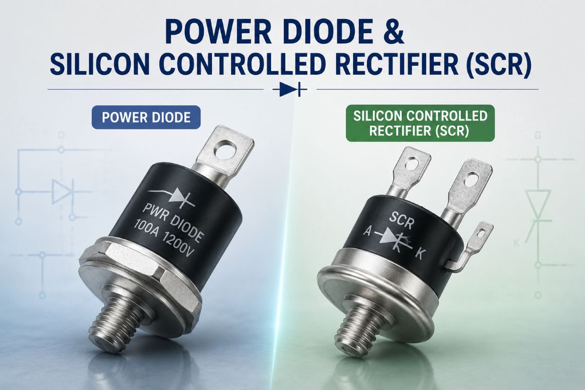
A power diode is a semiconductor device used in power electronic circuits to allow current to flow mainly in one direction. It is designed to handle high current and high voltage, so it is commonly used in rectifiers, converters, and power supplies.
Operating Principle
In forward bias, the anode is positive with respect to the cathode, so the diode conducts current. In reverse bias, it blocks current, and only a very small leakage current flows. When reverse voltage becomes too high, breakdown may occur.
Types of Power Diode
- General-purpose rectifier diode: Used in AC to DC conversion.
- Fast-recovery diode: Used in high-frequency switching circuits.
- Schottky diode: Offers low forward voltage drop and fast switching. Available up to 100V, 300A, with more leakage current at high voltage
- Zener diode: Used for voltage regulation and protection.
V-I Characteristic
The V-I characteristic of a power diode shows the relation between diode voltage and current.
- In forward bias, current increases very slowly at first.
- After the cut-in voltage, the current rises sharply.
- In reverse bias, only leakage current flows.
- At breakdown voltage, reverse current increases rapidly.
Key Points
- High current handling capability.
- High reverse voltage blocking ability.
- Used in rectifiers and power control circuits.
- Built for reliable operation in power electronics.
Short Definition
A power diode is a high-power semiconductor device that conducts in one direction, blocks reverse current, and is widely used in rectification and power control applications.
Silicon Controlled Rectifier
What is an SCR?
A silicon controlled rectifier is a four-layer, three-junction semiconductor device used as a controlled switch in power electronics. It has three terminals: anode, cathode, and gate. Once turned on by a gate pulse, it remains conducting until the current falls below the holding current.
Working Principle
In forward-blocking mode, the SCR blocks current even when a forward voltage is applied. When a gate pulse is applied, the device turns on and conducts heavily in forward-conduction mode. It cannot be turned off by the gate, so a special turn-off method called commutation is required.
Why Commutation is Needed
Commutation means turning OFF the SCR after it has started conducting. This is essential in DC circuits and power control circuits because an SCR stays ON until its current is reduced below the holding level or a reverse voltage is applied.
Types of Commutation
SCR commutation is mainly divided into two broad groups:
>Natural commutation: The SCR turns off automatically in AC circuits when the current naturally reaches zero.
>Forced commutation: An external circuit is used to force the SCR current below the holding current or apply reverse voltage.
Forced Commutation Classes>
Class A: Load commutation.Class B: Resonant pulse commutation.
Class C: Complementary commutation.
Class D: Auxiliary commutation.
Class E: External pulse commutation.
Class F: Line commutation, also called natural commutation.
Simple Use of Each
>AC systems usually use natural commutation.
>DC circuits usually need forced commutation.
>Inverters and choppers commonly use forced methods.
>Choice depends on circuit type, switching speed, and control needs.
One-Line Definition
Commutation of an SCR is the process of turning it OFF by reducing its current below the holding current or by applying reverse voltage.