
Industrial 4–20 mA Loop and HART Communication-Complete Guide
📘 Industrial 4–20 mA Loop and HART Communication-Complete Guide
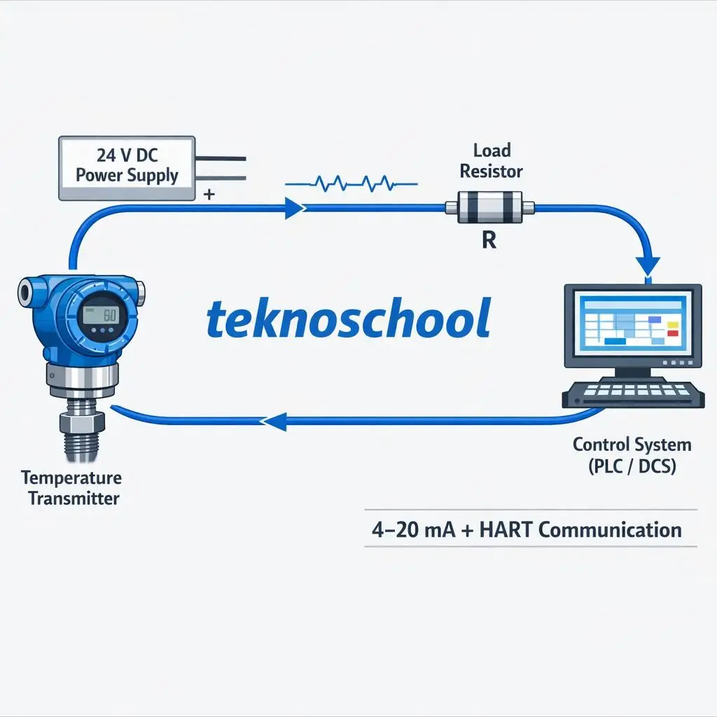
🔧 What Is a 4–20 mA Loop?
• Industry standard for transmitting process values• 4 mA = Lower Range Value (0%)
• 20 mA = Upper Range Value (100%) • Transmitter controls the loop current based on PV
• DCS reads this current and converts it to engineering units• Very fast, stable, and noise‑immune
• Works reliably over long distances• Ideal for PID control loops. The 4–20 mA loop is the backbone of industrial control. It provides a continuous, real‑time signal that the DCS uses for control decisions. Even if digital communication exists, the analog loop remains the primary control signal.
🛰 What Is HART Communication?
• Digital signal superimposed on the 4–20 mA loop• Uses FSK (Frequency Shift Keying)
• Does NOT disturb the analog signal
• Carries:
▸ Digital PV▸ Secondary variables (SV, TV, QV)
▸ Device diagnostics▸ Configuration data
• Slower than analog• Not suitable for PID control. HART is like a “digital layer” riding on top of the analog signal. It gives access to extra information without affecting the main 4–20 mA loop. This is why HART is used for configuration and diagnostics, not control.
🎛 How DCS Reads 4–20 mA Analog Data
Transmitter outputs 4–20 mA
DCS input card contains a 250 Ω resistor
Current is converted to voltage
• 4 mA → 1.0 V• 20 mA → 5.0 V
ADC converts voltage to digital value
DCS scales it to engineering units
SCADA displays this value
PID uses this analog PV
The DCS never measures current directly. It measures voltage across a resistor and calculates the current. This analog value is what drives the control loop.
🛰 How DCS Reads HART Digital Data
HART ripple rides on the 4–20 mA loop
HART modem inside the input card demodulates the signal
Extracts:
▸ Digital PV▸ SV, TV, QV
▸ Sensor temperature▸ Device diagnostics
DCS exposes these as additional tags
Used for maintenance, not control
HART-enabled cards can read both analog and digital data. The analog PV is used for control, while the digital data is used for monitoring and troubleshooting.
🖥 What SCADA Displays
Default Display:
✓ Analog PV (from 4–20 mA) ✓ Fast, stable, real‑time
Optional (If configured):
• HART PV• Sensor temperature
• Device status• Diagnostics
Control Loop Source: ✓ ALWAYS uses analog PV. SCADA normally shows the analog value because it is the most reliable and real‑time. HART values are optional and used mainly for diagnostics.
🔌 Single HART vs Multi‑Drop Mode
► Single HART (Address 0)
• Outputs 4–20 mA• HART digital available
• Suitable for PID control• One transmitter per loop
► Multi‑Drop Hart Mode (Address 1–15) • All transmitters fixed at 4 mA
• Only digital HART used• NOT suitable for PID
• Up to 15 transmitters on one loop• Used for monitoring only. In multi‑drop mode, the analog signal is disabled (fixed at 4 mA). This makes it impossible to use for control loops.
⚠ Why PID Cannot Work in Multi‑Drop Hart Mode
• No analog 4–20 mA PV available
• All devices output fixed 4 mA• HART is too slow for control
• HART is non‑deterministic• PID requires continuous real‑time PV. PID needs a fast, continuous signal. HART is slow and polled, so it cannot support real‑time control.
🧠 Solutions for PID + Multi‑Drop
SOLUTIONS FOR PID + MULTI‑DROP HART MODE✔ Option 1: Use separate 4–20 mA loops for each PID transmitter, HART multi drop for configuration calibration only✔ Option 2: Use FOUNDATION Fieldbus / Profibus PA (Multiple devices + digital control). We cannot run PID on multi‑drop.
📌 Applications of 4–20 mA Loop
• PID control loops
• Pressure / Flow / Level / Temperature control• Safety loops (SIS)
• Long‑distance transmission• Harsh industrial environments
• Valve position feedback• Real‑time process control. Any loop requiring fast response or safety integrity must use 4–20 mA.
📌 Applications of HART Communication
• Device configuration• Calibration
• Diagnostics & health monitoring• Predictive maintenance
• Multi‑drop monitoring• Reading SV, TV, QV
• Smart valve diagnostics• Asset management (AMS). HART is a maintenance and configuration tool. It enhances the analog loop but does not replace it.
🎯 Final Summary
4–20 mA (Analog)
✓ Fast✓ Real‑time
✓ Used for PID✓ One device per loop.
HART (Digital)
✓ Diagnostics✓ Extra variables
✓ Multi‑drop capable✗ Not used for PID