Maintenance of Gas Turbine
Gas Turbines
Fast, compact, and surprisingly fuel-flexible — gas turbines are the high-speed workhorses of standby and peaking power generation. Here is everything you need to understand them.
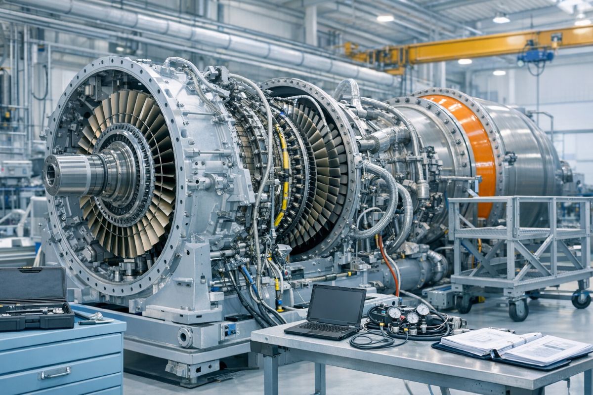
There is nothing quite like a gas turbine at full speed. Where diesel engines rumble and pulse, a gas turbine spins with a high-pitched, continuous roar — its compact rotating mass turning at speeds that would shred most mechanical equipment. Also called combustion turbines, these machines are a fixture in standby power, peaking power plants, and emergency generation at critical facilities ranging from military command centres to large industrial complexes.
Gas turbines have historically had one major disadvantage: high fuel consumption, particularly in small units under 10,000 kW at part load and when inlet air temperatures rise. This has made them less attractive than diesel engines for continuous prime power duty. But where low installed cost matters more than fuel efficiency — standby and peak-shaving applications — gas turbines win every time. Their simple cycle (open cycle) design dominates power plant installations, and that is the configuration explored here.
🔬
The Brayton Cycle — How a Gas Turbine Actually Works
Every gas turbine is built around the Brayton (or Joule) cycle, a four-step thermodynamic process that converts fuel energy into shaft rotation with remarkable speed and elegance. Understanding this cycle is the foundation of understanding everything about gas turbine performance and maintenance.
Ambient air is drawn in and compressed to 5–50 times atmospheric pressure with no heat transfer. The compressor section does the heavy work here, driven by energy extracted from the turbine.
Fuel is injected and ignited in the combustor at constant pressure, producing combustion gas temperatures of 700–1,400°C. This is where the energy input happens — and where blade material technology becomes critical.
Hot combustion gases expand through the power turbine back to atmospheric pressure, releasing energy. More energy is available here than was consumed in compression — the net difference is what drives the generator.
In an open cycle, exhaust gases are simply discharged to the atmosphere — there is no closed cooling loop. This is the simplest and most common design for power generation applications.
🔑 Efficiency Key: Thermal efficiency depends on three factors — compressor pressure ratio, turbine inlet temperature, and parasitic losses. The best modern large gas turbines achieve up to 40% efficiency at pressure ratios of 30–40 and temperatures around 1400°C. Typical units in power plant service run 20–33%, with room to improve as materials technology advances.
🏗️
The Three Core Sections
Strip away the auxiliary systems, and every gas turbine reduces to three fundamental sections working in sequence. Each one is a precision engineering achievement, and each one demands careful maintenance attention.
💨
The compressor draws in massive quantities of ambient air — typically four to five times more than a diesel engine of the same power rating — and pressurizes it to 10–50 times the inlet pressure. This enormous air demand means gas turbines require significantly larger air filters, intake ducts, and exhaust passages than comparable diesels. Blade deposits from contaminated inlet air are one of the most common causes of efficiency degradation, making inlet air filtration one of the most maintenance-sensitive aspects of the entire machine.
🔥
Compressed air enters the combustor, where fuel is injected through the fuel manifold, and igniters spark the mixture. Combustion occurs at constant pressure, generating gas temperatures between 700°C and 1,000°C. The combustor and turbine blades operate in an environment that would melt most metals — only advanced alloys and sophisticated blade cooling designs keep them intact. Fuel quality here is absolutely non-negotiable: any contamination, incorrect viscosity, or wrong fuel grade will cause rapid deterioration of injectors, blades, and liners.
⚡
Hot expanding gases pass through the power turbine, where their energy is converted into shaft rotation. The turbine produces enough power to simultaneously drive the compressor and deliver net work to the generator. Smaller units use a single-shaft design with the compressor and power turbine on one common shaft. Larger units often employ a two-shaft arrangement where the compressor turbine and power turbine are on separate shafts — allowing the compressor to vary speed independently and improving part-load efficiency.
🔩
Auxiliary Systems & Components
Gas turbines use compressed air (150–500 psig), DC electric motors powered by dedicated batteries, or hydraulic systems driven by a diesel engine or small auxiliary turbine. Regardless of method, the goal is the same: spin the turbine to ignition speed before burners fire, then accelerate to operating rpm.
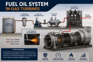
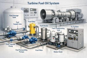
The packaged fuel system includes a motor-driven booster pump, duplex low-pressure filter, turbine-driven main pump, high-pressure filter, governor-regulated fuel control valve, and fuel manifold with injectors. Gas turbines accept a wider range of liquid fuels than diesels — kerosene, No. 1 and No. 2 fuel oil are all common.
Most gas turbines come with a complete self-contained lube system: air-cooled cooler, filter, pre/post-lube pumps, main engine-driven pump, heater, and oil storage tank. Oil change intervals are far longer than for diesels because combustion byproducts never contaminate the lube circuit. The same lube oil circuit also services the speed-reduction gear and the generator.
The governor controls turbine speed and fuel flow in real time as load changes. Mechanical-hydraulic and electronic governors are both used, but electronic governors with load-sharing capability are standard for multi-engine plants. As with diesel generators, compatible governors across all engines in a parallel configuration are a firm requirement.
Because gas turbines spin at 10,000–25,000 rpm, a speed reduction gear is essential to bring shaft speed down to generator-compatible synchronous speeds of 1,200–1,800 rpm. The gearbox is almost always an epicyclic (planetary or star compound) design, allowing a straight-through shaft arrangement that simplifies alignment. Two-stage reduction may be required for the fastest turbines.
Air demand is 4–5 times that of a diesel Engine of the same capacity, requiring substantially larger filtration and ducting. This is not optional maintenance — deposits on compressor and turbine blades directly reduce efficiency and power output. Inlet air quality is the single biggest controllable factor in gas turbine performance and blade life.
🚨
Alarm & Shutdown Reference
Gas turbines have a significantly more complex alarm and protection matrix than diesel engines, reflecting the higher temperatures, speeds, and vibrational stresses involved. Know which conditions are alarm-only and which trigger an automatic shutdown — your engine’s life may depend on it.
| System / Indication | ⚠️ Alarm Only | 🛑 Alarm + Shutdown |
|---|---|---|
| 🔥 Engine System | ||
| Impending High Blade Temperature | ✔ | |
| High Blade Temperature | ✔ | |
| Overspeed — Power Turbine | ✔ | ✔ |
| Ignition Failure / Fail to Start | ✔ | |
| High Vibration — Engine | ✔ | ✔ |
| 🛢️ Lube System | ||
| High Oil Temperature | ✔ | ✔ |
| Low Oil Pressure | ✔ | ✔ |
| Lube Filter High Differential Pressure | ✔ | |
| ⛽ Fuel System | ||
| Liquid Fuel Filter High Differential Pressure | ✔ | ✔ |
| Low Liquid Fuel Pressure | ✔ | ✔ |
| ⚡ Generator System | ||
| High Generator Winding Temperature | ✔ | ✔ |
| High Vibration — Gearbox | ✔ | ✔ |
| Low Battery Voltage / Battery Charger Failure | ✔ | |
| Inlet Air Filter — High Differential Pressure | ✔ | |
🔗
System Interfaces
A gas turbine is the hub of a network of supporting systems. Each interface represents both a performance dependency and a maintenance responsibility. A weakness in any one of these systems will show up as turbine performance degradation, accelerated wear, or outright failure at the worst possible moment.
Proper mechanical alignment between the turbine output shaft and the generator is fundamental. The engine-generator combination must be matched by the manufacturer, with a direct or flexible coupling installed and verified. Misalignment at these operating speeds causes catastrophic vibration and rapid bearing failure.
Gas turbines accept kerosene, No. 1, and No. 2 fuel oil — a broader range than most diesels. The fuel must meet the engine manufacturer’s specification for viscosity, contamination, and water content. Fuel system cleanliness directly protects injectors and combustor hardware from the most expensive failures.
Because combustion byproducts never enter the lube circuit in a gas turbine (unlike a diesel), oil change intervals are considerably longer. Regular oil analysis is still essential for detecting early signs of bearing wear or contamination. The lube system serves the turbine, gearbox, and generator in a single integrated circuit.
Any restriction to intake or exhaust flow directly reduces turbine output. Inlet air systems may incorporate preheating for cold climates or moisture separation for humid coastal environments. Monitoring the inlet filter differential pressure alarm is one of the most important daily operational checks for gas turbine maintenance staff.
Starting air pressures for gas turbines range from 150 to 500 psig, depending on the unit, higher than typical diesel starting systems. If DC electric starting is used, battery condition monitoring and charger reliability become critical maintenance items. Hydraulic starting systems add their own maintenance requirements for the prime mover, pump, reservoir, and heat exchanger.
Modern gas turbine plants increasingly use automated data logging to capture operating conditions, flag out-of-tolerance readings, and record alarm histories. Whether manual or automated, trend analysis of key parameters — blade temperatures, vibration levels, lube oil pressure — is the foundation of proactive maintenance planning for any gas turbine installation.
Inlet Air Quality is Your Biggest Lever
For diesel engines, lube oil and fuel quality dominate the maintenance conversation. For gas turbines, inlet air cleanliness is the most impactful single maintenance variable. Dust, salt, and moisture deposits on compressor and turbine blades cause a gradual, hard-to-detect efficiency loss. Each percentage point of efficiency lost costs real money every hour the turbine runs. Regular blade washing (online and offline), filter inspection, and differential pressure monitoring are not optional procedures. They are the front line of gas turbine protection.
Combine that with a rigorous data logging practice — tracking vibration signatures, bearing temperatures, and lube oil analysis results over time — and you have the foundation of a predictive maintenance programme that will keep your gas turbine delivering reliable power for decades.