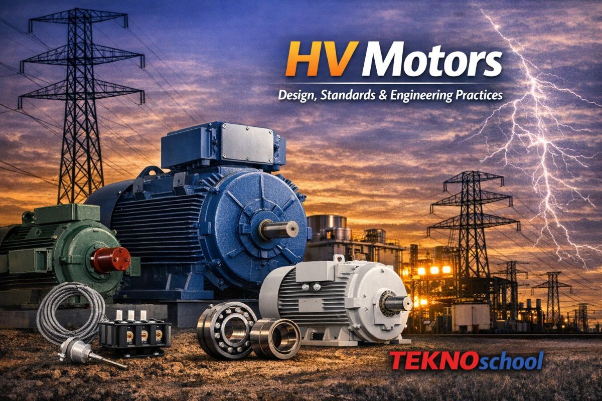
HV Motors – Design, Standards, and Engineering Practices
HV Motors – Design, Standards, and Engineering Practices
⚙️ Introduction
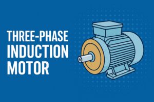
High‑voltage (HV) induction motors are the backbone of heavy industrial operations — driving compressors, pumps, blowers, and crushers with precision and reliability. Defines a comprehensive framework for the design, manufacture, testing, and certification of HV motors used in demanding environments such as refineries, petrochemical plants, and metallurgical facilities.
📘 Scope
The specification covers all aspects of design, assembly, factory wiring, inspection, testing, and delivery of HV induction motors. It ensures that every motor supplied meets project‑specific conditions and integrates seamlessly with other electrical and mechanical systems.
📏 General Requirements
Operating Conditions
Motors must operate reliably under site‑specific ambient conditions — typically 40 °C temperature and 1000 m altitude. They are designed for tropical, humid, and corrosive atmospheres.
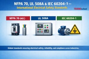
Applicable Standards
The specification references both international and Indian standards, ensuring global compatibility.
| Category | Standard | Description |
|---|---|---|
| General | IEC 60034 | Rotating electrical machines |
| Indian Standards | IS 325 | Three‑phase induction motors |
| IS 1271 | Thermal evaluation of insulation | |
| IS 2148 | Flameproof enclosures | |
| IS 4691 | Degree of protection (IP ratings) | |
| IS 12065 | Noise limits for rotating machines | |
| IS 12075 | Vibration measurement and limits | |
| IS 13555 | Motor selection guide for driven equipment |
Priority Order in Case of Conflict:
- Statutory regulations
- Data sheets
- Job specifications
- This specification
- Codes and standards
This hierarchy ensures compliance with safety and legal requirements above all else.
⚡ Basic Requirements
Performance Criteria
- Continuous operation (S1 duty)
- Full‑voltage starting
- Service factor = 1.0
- Spare‑part support for 15 years minimum
Efficiency and Design
High efficiency is mandatory. Vendors may offer alternate high‑efficiency models for each horsepower and speed category.
Voltage and Frequency Tolerance
Motors must operate continuously at rated output under:
- Voltage variation ± 6 %
- Frequency variation ± 3 %
- Combined variation within permissible limits
🔄 Starting and Torque Characteristics
| Parameter | Up to 500 kW | 500–1000 kW | Above 1000 kW |
|---|---|---|---|
| Cold starts | 3 | 3 | 2 |
| Hot starts | 2 | 2 | 1 |
Additional design requirements:
- Starting current ≤ 600 % of rated current
- Pull‑out torque ≥ 175 % of rated load torque
- High‑torque motors for heavy‑duty drives (compressors, crushers, blowers)
- Re‑acceleration capability after voltage dips
🔁 Direction of Rotation
Motors should ideally support bi‑directional rotation.
- Clockwise rotation (viewed from coupling end) corresponds to phase sequence A‑B‑C.
- Counter‑clockwise rotation is achieved by reversing the phase sequence.
- Permanent corrosion‑resistant arrows indicate direction.
🔋 Insulation and Temperature Rise
| Parameter | Requirement |
|---|---|
| Insulation Class | F (temperature limit 155 °C) |
| Temperature Rise | Limited to Class B (80 °C above ambient 40 °C) |
| Tropicalization | Vacuum‑impregnated windings |
| Surge Withstand | 2.4 × rated peak‑to‑line voltage |
| Impulse Voltage | As per IS 14222 |
This ensures long‑term reliability even under high thermal and electrical stress.
🔈 Noise and Vibration Limits
- Noise level ≤ 85 dBA (ISO 1680‑2)
- Vibration severity within IS 12075 limits
- Motors with sleeve bearings include proximity probes for vibration monitoring.
🧱 Mechanical Requirements
Enclosures
- Safe areas: Industrial type, IP‑55 protection
- Hazardous areas: Ex‑d, Ex‑e, Ex‑p, or Ex‑n protection
- All metallic parts exposed to air must be corrosion‑resistant or treated.
- Bonding straps prevent sparking due to circulating currents.
Mounting
- Horizontal motors: Foot‑mounted
- Vertical motors: Flange‑mounted
Shaft and Coupling
- Single shaft extension with key‑way and key
- Designed for easy coupling with driven equipment
🛢️ Bearing and Lubrication Systems
| Type | Description | Key Features |
|---|---|---|
| Grease‑lubricated bearings | Standard for most motors | Labyrinth seals, online greasing |
| Sleeve bearings with oil rings | For continuous lubrication | Settling reservoir, overflow plug, level indicator |
| Forced lubrication bearings | For large motors or high‑temperature applications | Independent oil system with pumps, coolers, filters, and alarms |
Forced Lubrication System Components:
- Dual pumps (one standby)
- Shell‑and‑tube oil cooler (admiralty brass tubes)
- Stainless‑steel reservoir with 3‑minute retention time
- Duplex filters (≤ 25 µm)
- Temperature gauges, pressure indicators, alarms
- Electric immersion heater for cold starts
Bearing Insulation:
- Shaft voltage ≤ 250 mV (ball/roller) or ≤ 400 mV (sleeve)
- Non‑driving end bearing is insulated from the frame
🌬️ Cooling Systems
| Cooling Type | Description | Typical Use |
|---|---|---|
| Self‑ventilated | Fan‑cooled, corrosion‑resistant, anti‑static fans | Standard installations |
| Forced ventilation | Dual motor‑driven fans, full airflow redundancy | High‑output motors |
| Closed‑circuit water‑to‑air | Cupro‑nickel or admiralty brass heat exchangers | Large motors, outdoor use |
| Closed‑circuit air‑to‑air | Steel or aluminium exchangers, varnish‑baked surfaces | Dusty or corrosive environments |
All cooling systems include filters, drains, and trip/alarm devices for safe operation.
⚙️ Rotor and Construction Details
- Rotor bars are tightly fitted — no slot filler material.
- Non‑sparking fan impeller for hazardous areas.
- Shaft grounding brush at the mechanical output end.
- Double insulation at bearing seals to prevent shaft currents.
- Balance weights securely locked and visually inspectable.
🧰 Additional Mechanical Features
| Feature | Specification |
|---|---|
| Lifting Hooks | Provided for motor and heat exchanger |
| Earth Terminals | Two × 12 mm studs with nuts and washers |
| Finish | Epoxy‑based paint, rust‑inhibiting primer |
| Vertical Motors | Drip covers and baffles for liquid protection |
| Nameplates | Stainless steel, UL‑approved, includes service factor, bearing data, weight, and lubricant grade |
⚡ Electrical Requirements
Terminal Boxes
- Cast‑iron or steel (≥ 3 mm thick)
- Rotatable in 90° steps for flexible cable entry
- Explosion‑proof joints for Ex‑d motors
- Separate boxes for heaters and thermostats
- Solder‑less compression connectors and clamp terminals
Wire Marking
Shrink‑sleeve markers with identical numbering on equipment and drawings per IS 4728.
🔧 Accessories
| Accessory | Function | Specification |
|---|---|---|
| RTDs (Resistance Temperature Detectors) | Measure winding and bearing temperature | Platinum 100 Ω sensors, 2 per phase + 1 per bearing |
| Differential CTs | Protection for motors ≥ 1100 kW | 3 flux‑balance CTs, ratio 100:5, accuracy PS |
| Vibration Probes | Shaft vibration monitoring | Bentley‑Nevada 7200 series |
| Surge Protection | Prevent voltage spikes | Capacitors + arresters in the terminal box |
| Space Heaters | Prevent condensation |