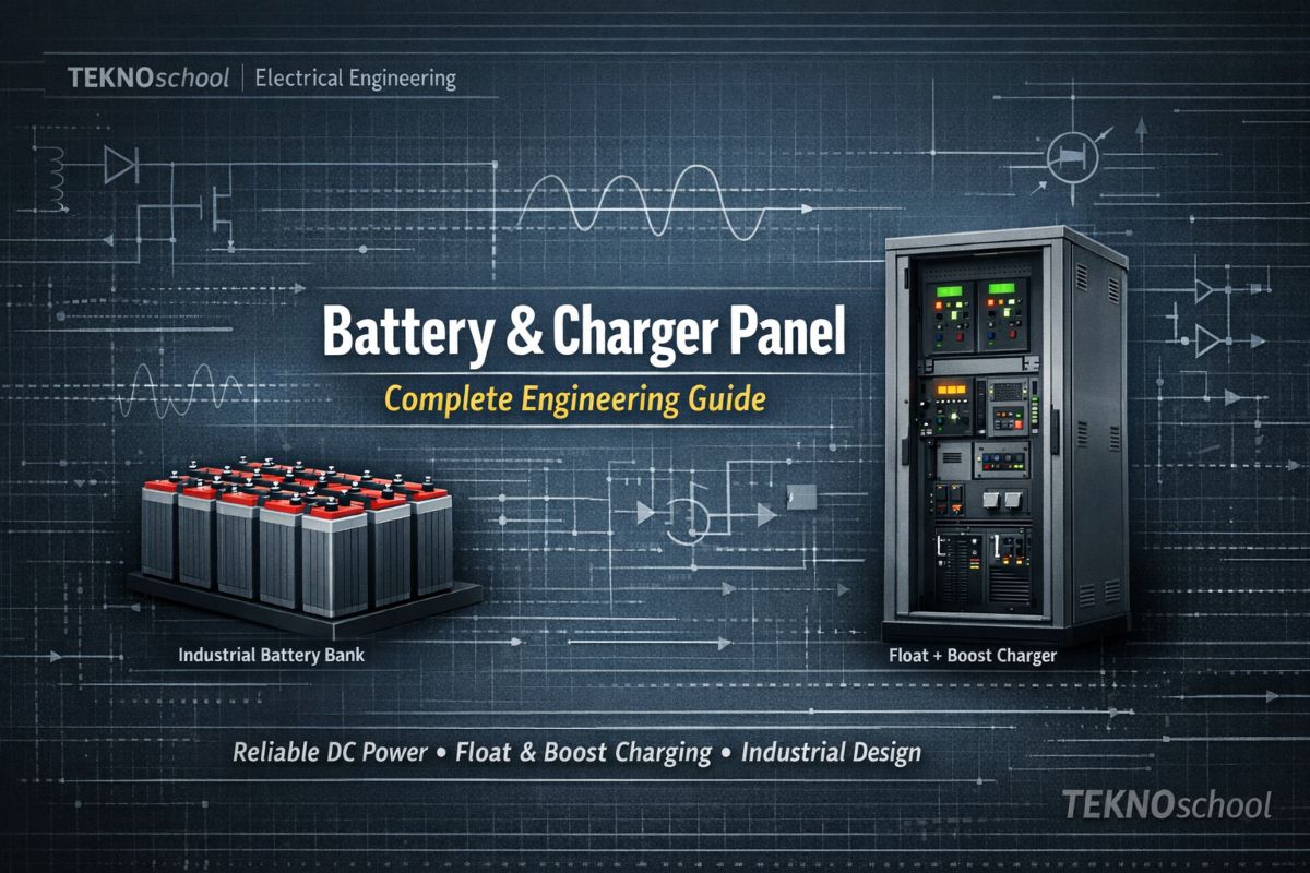
Industrial Battery and Charger Panel:Design & Engineering Guide
Industrial Battery & Charger Panels: Engineering Guide
Reliable Industrial Battery and Charger Panel is the silent backbone of every industrial plant. From emergency shutdown systems to instrumentation loops and communication networks, countless critical functions depend on a stable and uninterrupted DC supply. To achieve this, industries deploy a combination of Industrial Battery & Charger Panels and DC distribution panels engineered for long‑term, trouble‑free operation.
This guide breaks down the essential engineering principles, design requirements, and best practices for industrial battery and charger panels. Whether you’re an engineer, consultant, or maintenance professional, this comprehensive overview will help you understand how these systems are designed, sized, and integrated into plant infrastructure.
1. Purpose of Battery & Charger Systems
Industrial DC systems must deliver:
- Continuous power to critical loads
- Automatic backup during AC failures
- Stable voltage under varying load conditions
- Safe charging and long battery life
- Easy monitoring, maintenance, and fault detection
A well‑designed system ensures that even during power disturbances, the plant’s essential functions remain unaffected.
2. Key Components of the System
A complete DC power system typically includes:
- Battery bank (Lead‑acid, VRLA, or Ni‑Cd)
- Two independent battery chargers
- DC distribution board (DCDB)
- Accessories, protection devices, and monitoring instruments
This redundancy ensures reliability even if one charger fails or the AC supply is interrupted.
3. Battery Engineering Essentials
3.1 Battery Sizing
Battery capacity must be calculated based on:
- Minimum ambient temperature
- Duty cycle requirements
- Ageing factor (commonly 0.8)
- End‑of‑discharge voltage limits
The battery voltage should not drop below 90% of nominal at the end of the duty cycle.
3.2 Battery Types
Common industrial choices include:
- Lead‑acid tubular plate batteries
- Nickel‑cadmium pocket plate batteries
- VRLA batteries for maintenance‑free applications
Each type has unique characteristics in terms of life, maintenance, and charging behavior.
3.3 Charging Requirements
Industrial batteries must support:
- Float charging for continuous operation
- Boost charging to recover from a deep discharge
- Quick charging (especially for VRLA and Ni‑Cd)
A typical requirement is the ability to reach full charge from a fully discharged state within 10 hours.
3.4 Battery Accessories
A complete battery installation includes:
- Wooden or FRP stands
- Inter‑cell and inter‑row connectors
- Electrolyte for initial filling
- Hydrometer, thermometer, and safety gear
- Insulators and identification plates
These ensure safe installation and long‑term maintainability.
4. Battery Charger Architecture
Industrial systems use two chargers:
- Charger‑1: Primary float charger
- Charger‑2: Float + Boost charger (standby + boost mode)
This dual‑charger philosophy ensures an uninterrupted DC supply.
4.1 Charger‑1 (Float Charger)
Key features include:
- Solid‑state design
- Constant voltage, current‑limiting
- Output stability within ±1%
- 3‑phase half‑controlled rectifier (3 diodes + 3 thyristors)
- Independent current limit for internal faults
Charger‑1 normally powers the load while maintaining the battery on float.
4.2 Charger‑2 (Float + Boost Charger)
Charger‑2 must be sized for the higher of:
- Boost charging the battery in 10 hours
- Float charging while feeding the full DC load
It includes transformer taps for voltage adjustments and supports manual selection between float and boost modes.
4.3 Common Features for Both Chargers
- Ripple content < 3%
- High‑speed semiconductor fuses
- Blocking diodes to prevent back‑feeding
- Interlocks between float and boost modes
- Forced cooling alarms (if applicable)
- Complete interconnections between chargers
A special diode arrangement ensures that even during boost charging, the DC load continues to receive power from the 80% battery tap.
5. Control, Metering & Annunciation
5.1 Control Features
Both chargers include:
- Auto/Manual selector
- Coarse and fine voltage controls
- Start/Stop pushbuttons
- Float/Boost selector (for Charger‑2)
These controls allow precise voltage regulation and operational flexibility.
5.2 Metering
Typical metering includes:
- AC input voltmeter and ammeter
- DC output voltmeter and ammeter
- Battery voltmeter and ammeter
- Earth leakage ammeter
Meters are typically of an accuracy class 1.0 and protected against reverse currents.
5.3 Annunciation System
A robust audio‑visual alarm system alerts operators to:
- DC undervoltage
- DC overvoltage
- Earth leakage
- AC supply failure
- Fuse failures
- Overload
- Charger failure
Each charger also provides a summary alarm contact for remote monitoring.
6. Panel Construction Requirements
The charger and DCDB panels must be:
- Fabricated from 1.6–2 mm sheet steel
- Provided with ventilation louvers
- Rated for IP‑31 protection
- Equipped with double‑compression brass cable glands
- Fitted with color‑coded busbars
- Fully shrouded for operator safety
Internal wiring uses 2.5 mm² copper conductors, and all instruments are back‑connected for reliability.
7. Additional Panel Features
7.1 Space Heaters
To prevent moisture condensation, each panel includes:
- Space heater
- Thermostat
- Manual switch
7.2 Internal Lighting
Each vertical panel has:
- Internal lamp
- Door‑operated switch
7.3 Maintenance Socket
A 240V socket is provided for tools and testing equipment.
8. Testing & Quality Assurance
Before dispatch, the system undergoes:
- Voltage regulation tests
- Insulation resistance tests
- Power loss and power factor measurement
- Temperature rise tests
- Trigger circuit verification
- Coordination checks for stabilization circuits
Panels must withstand 2 kV for 1 minute, ensuring electrical robustness.
9. Documentation & Drawings
A complete engineering package includes:
- GA drawings
- SLDs
- Datasheets
- Bill of materials
- Test certificates
- Operation & maintenance manuals
This ensures smooth installation, commissioning, and long‑term operation.
Conclusion
Battery and charger panels are mission‑critical components in industrial power systems. Their design must balance reliability, safety, redundancy, and maintainability. By following established engineering practices—such as dual‑charger architecture, precise battery sizing, robust panel construction, and comprehensive monitoring—plants can ensure uninterrupted DC power for their most essential systems.