Three Phase Induction Motor Complete Guide
⚙️ WHAT IS IT AND HOW DOES IT WORK?
The Foundation of Modern Industry 🏭
A three-phase induction motor is the most common electric motor in the world, powering everything from small workshop fans to giant industrial crushers. It’s called an “induction” motor because it works through electromagnetic induction—no physical electrical connection to the rotating part is needed.
The Simple Working Principle 🧲
Imagine a magnet spinning around a metal disk. The spinning magnet will drag the disk along with it. That’s essentially how this motor works!
Here’s what happens step by step:
1️⃣ Three-Phase Power Enters → You connect three electrical phases (120° apart) to the motor’s outer stationary part called the stator
2️⃣ Rotating Magnetic Field is Born 🌀 → These three phases create a magnetic field that physically rotates in space, even though nothing is moving yet
3️⃣ Rotor Gets Induced ⚡ → This rotating magnetic field cuts through the conductors in the inner rotating part (rotor), generating electric current in them automatically
4️⃣ Rotor Follows 🔄 → The induced current in the rotor creates its own magnetic field, which interacts with the stator’s rotating field, pulling the rotor to spin
5️⃣ But Never Catches Up → The rotor always spins slightly slower than the rotating magnetic field. This speed difference (called “slip”) is essential—without it, there would be no induction and no torque
Why It’s Brilliant:
No brushes or electrical connections to the rotor
Self-starting (just switch on!)
Simple and extremely robust
Works for decades with minimal maintenance
🏗️ MAIN TYPES OF THREE-PHASE INDUCTION MOTORS
There are two fundamental types based on rotor construction:
🐿️ SQUIRREL CAGE INDUCTION MOTOR (90% of all motors)
What it looks like: The rotor has thick aluminum or copper bars embedded in it, connected at both ends by rings—looks like a hamster exercise wheel, hence the name!
Key Features:
✅ Advantages:
Extremely simple and rugged
No maintenance needed
Lower cost
Most reliable motor ever made
No brushes or slip rings
❌ Disadvantages:
High starting current (5-8 times normal)
Difficult to control speed without electronics
Fixed starting torque characteristics
Best for: General purpose applications—pumps, fans, compressors, conveyors, machine tools. This is your “default” motor choice.
Voltage Range:
Low Voltage (LV): 230V, 400V, 415V, 460V, 690V
High Voltage (HV): 3.3kV, 6.6kV, 11kV for large power needs
🔗 SLIP RING (WOUND ROTOR) MOTOR (10% of motors, special applications)
What it looks like: The rotor has actual copper windings (like the stator), and these windings are connected to three slip rings on the shaft. Carbon brushes touch these rings, allowing external connections.
Key Features:
✅ Advantages:
Excellent starting torque with low current
Smooth, controlled acceleration
Can adjust speed by adding external resistance
Perfect for heavy-duty starts
❌ Disadvantages:
More expensive
Brushes and slip rings need regular maintenance
More complex construction
Best for: Heavy-duty, high-torque applications—cranes, hoists, crushers, ball mills, large compressors where loads are difficult to start.
🧱 CONSTRUCTION AND MATERIALS
Think of the motor as having two main parts: a stationary outer part (stator) and a rotating inner part (rotor), separated by a tiny air gap.
🏠 THE STATOR (Stationary Outer Part)
Frame/Housing:
Material: Cast iron (heavy-duty), fabricated steel, or aluminum (small motors)
Purpose: Protects everything inside, provides structural strength, and acts as a mounting base
LV vs HV: HV motors have much heavier, reinforced frames
Stator Core:
Material: Thin sheets (0.35-0.5mm) of silicon steel stacked together
Why laminated? To reduce energy losses from swirling currents (eddy currents)
Purpose: Creates the magnetic highway for flux to travel
Stator Windings:
Material: Copper wire (sometimes aluminum in very cheap motors)
Insulation:
LV motors: Class F insulation (withstands 155°C), coated with enamel and varnish
HV motors: Class H insulation (withstands 180°C), uses mica tape, special epoxy resin, and vacuum-pressure treatment for extreme voltage endurance
🔄 THE ROTOR (Rotating Inner Part)
For Squirrel Cage Type:
Bars: Aluminum (die-cast, economical) or copper (premium, more efficient)
End Rings: Short-circuit all the bars together
Core: Same laminated silicon steel as stator
For Wound Rotor Type:
Windings: Copper coils similar to stator, carefully wound
Slip Rings: Three brass/steel rings mounted on the shaft
Brushes: Carbon blocks that rub against slip rings to make external connections
🔧 OTHER ESSENTIAL PARTS
Shaft:
High-grade carbon steel or alloy steel
Must be perfectly straight and balanced
Transmits all the mechanical power to your load
Bearings:
Small motors: Ball bearings (smooth, quiet)
Large motors: Roller bearings (handle heavy loads)
Lubrication: Grease (sealed for life or re-greasable) or oil bath
Terminal Box:
Cast aluminum or sheet metal box
Houses connection terminals
Contains links to configure star (Y) or delta (Δ) connection
Keeps electrical connections safe and weatherproof
Cooling Fan:
External fan mounted on shaft (for enclosed motors)
Internal fan for open motors
Circulates air to remove heat
Air Gap:
The tiny space between stator and rotor (0.5-2mm)
Critical for motor performance
Too large: poor efficiency, low power factor
Too small: risk of rubbing
🔍 HOW EACH PART OPERATES
| Part | What It Does | Why It Matters |
|---|---|---|
| 🏠 Frame | Houses everything, provides mounting, dissipates heat | Structural integrity, environmental protection |
| 🧲 Stator Core | Carries the rotating magnetic flux | The “magnetic highway” with minimal losses |
| 🔌 Stator Windings | Generate the rotating magnetic field when energized | This is where the magic starts—creates the RMF |
| 🌪️ Air Gap | Transfer zone for magnetic energy | Magnetic energy crosses here from stator to rotor |
| 🔄 Rotor Core | Provides path for induced magnetic flux | Completes the magnetic circuit |
| ⚡ Rotor Conductors | Carry induced current, create rotor magnetic field | Induced current here produces torque |
| 🔩 Shaft | Delivers mechanical power to load | Your connection to the real world |
| ⚙️ Bearings | Support rotation, maintain alignment | Keep rotor centered in air gap |
| 🌬️ Fan | Removes heat generated in motor | Prevents overheating |
| 📦 Terminal Box | Safe electrical connections | Where you wire up the motor |
🔌 UNDERSTANDING MOTOR PERFORMANCE (SIMPLIFIED)
The Equivalent Circuit Concept
Think of the induction motor like a transformer with a rotating secondary. Here’s the simple energy flow:
Power Flow Path: 🌊
Electrical Input → Stator Copper Losses (wire heating) → Magnetic Field (air gap) → Rotor Copper Losses → Mechanical Output + Friction Losses
Key Concepts:
1️⃣ Magnetizing Current → A portion of current just creates the magnetic field (reactive power, no real work done)
2️⃣ Stator Losses → Some power lost heating up stator windings
3️⃣ Air Gap Power Transfer → Majority of power crosses magnetically to rotor
4️⃣ Rotor Losses → Some power lost in rotor resistance (especially during start)
5️⃣ Mechanical Output → What’s left drives your load
At Startup:
High rotor current (rotor not moving, like a shorted transformer)
High losses
Low efficiency
Low output
At Running Speed:
Low rotor current (rotor almost catching up)
Low losses
High efficiency (85-96%)
Full power output
📈 TORQUE-SPEED RELATIONSHIP (THE MOTOR’S CHARACTER)
If you plot how much torque the motor produces at different speeds, you get a curve that tells you everything about the motor’s personality.
Key Points on the Journey from Standstill to Full Speed:
🔴 Starting Point (Speed = 0)
Starting Torque kicks in when you energize the motor
Squirrel cage: Moderate (1.5-2x rated torque)
Slip ring with added resistance: High (2-2.5x rated torque)
Must be enough to overcome load friction and start moving
🟡 Pull-Up Region (Acceleration Phase)
As motor speeds up, torque may dip slightly
This is the “danger zone” for high-inertia loads
Motor must have enough torque here to keep accelerating
🟢 Peak Torque Point (Breakdown/Pull-Out Torque)
Maximum torque the motor can ever produce
Typically 2-3x rated torque
Occurs around 80-90% of synchronous speed
This is your safety margin for overloads
🔵 Normal Running Zone (Full Load Point)
Where the motor lives its life
Runs at 2-5% slip (e.g., 1440 RPM for a 4-pole 50Hz motor instead of 1500 RPM)
Stable: if load increases slightly, motor slows a bit, producing more torque to match
High efficiency zone
⚫ Light Load (Approaching Synchronous Speed)
Very little slip
Torque drops toward zero
Motor can never actually reach synchronous speed (would mean zero slip, zero induction, zero torque)
The Stable Operating Region ✅
Right side of the peak (from rated point toward synchronous speed)
Self-regulating: load goes up → speed drops slightly → torque increases automatically
This is where motors normally operate
Effect of Rotor Resistance:
Higher resistance: Higher starting torque, but lower efficiency at running speed, peak shifts to lower speeds
Lower resistance: Lower starting torque, higher efficiency, peak at higher speeds
Slip ring motors exploit this by adding resistance during start, then removing it
🚀 STARTING BEHAVIOR
When you first energize a motor, here’s the sequence:
First 0.1 Seconds (The Rush):
Massive current spike (5-8x normal)
Rotor is stationary, maximum slip
Building up the magnetic field
Like a short circuit initially
Next 1-5 Seconds (Acceleration):
Current gradually decreases as speed builds
Rotor catches up with rotating field
Slip reduces, rotor impedance increases
Torque must overcome load inertia and friction
Final Phase (Settling):
Current drops to rated value
Speed stabilizes at design slip point
Motor settles into steady operation
Curve Shape Differences:
Standard Squirrel Cage: Moderate starting torque with potential dip mid-acceleration
Deep Bar/Double Cage Design: Higher starting torque using skin effect (current concentrates at bar edges when rotor current frequency is high)
Slip Ring with Resistance: Smooth, high torque throughout acceleration—like having an automatic transmission
🏷️ MOTOR NAMEPLATE—YOUR MOTOR’S ID CARD
Every motor has a nameplate with critical information. Here’s what it all means:
Electrical Information ⚡
Power Rating (kW or HP):
Motor’s mechanical output capability
Example: 15 kW = 20 HP
This is what it can deliver to the load continuously
Voltage & Connection:
Example: “415V Δ / 240V Y”
Means you can connect it in Delta (Δ) for 415V supply or Star (Y) for 240V supply
Most industrial: 415V Delta in India, 400V in Europe, 460V in USA
Current (Amps):
Full load current for each connection
Example: 28A (Delta), 48A (Star)
Size your cables and protection based on this
Frequency:
50 Hz (India, Europe, most of world)
60 Hz (USA, some Americas)
Motor speed depends on this
Speed (RPM):
Full load speed, not synchronous speed
Example: 1440 RPM for 4-pole, 50Hz motor
Calculated from synchronous speed minus slip
Power Factor:
Typically 0.85-0.90 lagging at full load
Tells you how much reactive power motor draws
Important for utility billing
Physical Information 🏗️
Frame Size:
IEC standard: 80, 90, 100, 112, 132, 160, 180, 200, 225, 250, 280, 315…
Defines mounting dimensions
Letter suffix: S (short), M (medium), L (long)
Mounting Type (IM Code):
IM B3: Foot-mounted, horizontal shaft
IM B5: Flange-mounted
IM B35: Foot and flange
Many other configurations
Number of Poles:
2-pole = 3000/3600 RPM (synchronous)
4-pole = 1500/1800 RPM
6-pole = 1000/1200 RPM
8-pole = 750/900 RPM
Duty Cycle:
S1: Continuous duty (most common)
S2: Short-time duty
S3-S10: Various intermittent duties
Protection & Environment 🌍
IP Rating (Ingress Protection):
Two digits: IP XY
First digit (X): Protection from solids
0 = No protection
5 = Dust protected
6 = Dust tight
Second digit (Y): Protection from liquids
0 = No protection
4 = Splash protected
5 = Water jet protected
6 = Powerful water jets
Most common: IP55 (dust protected, water jet protected)
Insulation Class:
Class F: Withstands 155°C (most common)
Class H: Withstands 180°C (HV motors, harsh environments)
Determines how hot windings can get
Cooling Method (IC Code):
IC411: Totally Enclosed Fan Cooled (TEFC)—most common
Other codes describe cooling arrangements
Ambient Temperature:
Usually rated for 40°C maximum ambient
If your location is hotter, motor must be derated
Altitude:
Standard rating: Up to 1000m above sea level
Higher altitudes need derating (thinner air, less cooling)
Efficiency & Standards 📊
Efficiency Class (IEC):
IE1: Standard efficiency (older motors)
IE2: High efficiency
IE3: Premium efficiency (current standard)
IE4: Super premium efficiency (latest)
Higher = less energy wasted
Service Factor:
Example: 1.15
Means motor can handle 15% overload continuously
Common in North America
Standards Compliance:
IEC 60034: International motor standard
IS 325: Indian standard
NEMA: North American standard
🔧 HOW TO INSTALL YOUR MOTOR PROPERLY
Before Installation ✅
Inspect the Motor:
Check for shipping damage
Rotate shaft by hand—should turn smoothly with slight resistance
Measure insulation resistance with megger (should be >1 MΩ)
Check bearing condition and lubrication
Prepare the Site:
Foundation must be firm, level, and able to handle vibration
Ensure adequate space around motor for cooling airflow
Area should be dry and protected from weather
Ventilation must be adequate
Mounting the Motor 🔩
Foundation Bolt Installation:
Use anchor bolts matching motor foot bolt holes
Level the motor precisely with a spirit level
Shim if necessary to achieve perfect level
For permanent installation, grout the base after alignment
Tighten bolts evenly in a cross pattern to avoid warping
Critical Shaft Alignment:
Align motor shaft to driven equipment shaft within tight tolerance
Check both parallel alignment (shafts parallel) and angular alignment (faces parallel)
Use dial indicators for precision
Misalignment causes premature bearing failure and vibration
Re-check alignment after bolting down
Electrical Connections ⚡
Wiring the Motor:
Use cable size appropriate for nameplate current rating
Verify supply voltage matches nameplate
Set star/delta links correctly in terminal box
Connect earth/ground wire securely—safety critical
Use proper cable glands to maintain IP rating
Terminal Box Setup:
Some motors allow terminal box rotation for convenient cable entry
Enter cables from bottom when possible (weather protection)
Ensure all seals and gaskets are in place
Tighten gland nuts properly
Check Rotation Direction:
Do a “bump test” (momentary energization)
Swap any two phases to reverse direction if needed
Verify correct direction before coupling to load
Cooling & Ventilation 🌬️
For TEFC (Enclosed) Motors:
Leave 10-15 cm clearance all around motor
Never block cooling fan or air vents
Keep cooling fins clean
Ensure fan cover is properly installed
For Open Motors:
Protect from dust and moisture
Ensure clean air supply
For Water-Cooled Motors:
Connect cooling water supply with proper filters
Set up temperature monitoring
Ensure water quality is suitable
Pre-Start Testing 🧪
Insulation Test: Megger reading >1 MΩ minimum
Rotation Check: Bump test to verify direction
Protection Check: Verify overload relays, contactors function
Current Balance: After start, check all three phases draw similar current (within 5%)
🛡️ PROTECTING YOUR MOTOR FROM THE ENVIRONMENT
IP Ratings Explained Simply 💧
The IP code tells you what the motor can handle:
Common IP Ratings for Motors:
| IP Rating | Where to Use | What It Protects Against |
|---|---|---|
| IP23 | Clean indoor only | Basic touch protection, light dripping water |
| IP44 | Indoor, some dampness | Splashing water, most tools |
| IP55 ⭐ | Indoor/outdoor standard | Dust, rain, hose jets—most common industrial choice |
| IP56 | Outdoor, dusty | Heavy dust, strong rain |
| IP65 | Washdown areas | Dust tight, low-pressure jets |
| IP66 | Harsh outdoor/marine | Dust tight, powerful high-pressure jets |
Simple Memory Aid:
IP55 = “Industrial Standard”—handles dust and water jets
IP65/66 = “Washdown Grade”—for food, pharma, marine use
Additional Weather Protection 🌧️
For Outdoor Motors:
Install rain hood or canopy even with IP55 rating
Enter cables from bottom to prevent water running in
Position drain plugs at lowest point, open periodically
Check and maintain breathers
Corrosion Protection:
Special paint systems for coastal/chemical environments
Stainless steel hardware in corrosive atmospheres
Regular inspection and touch-up painting
Temperature Extremes:
Cold (<0°C): Anti-condensation heaters, special cold-weather grease
Hot (>40°C): Derate motor or use higher insulation class
Consider motor temperature rise plus ambient when selecting
☠️ MOTORS FOR HAZARDOUS (EXPLOSIVE) AREAS
When motors operate in areas with flammable gases, vapors, or combustible dust, special explosion-protected motors are mandatory.
Understanding Zone Classification 🗺️
For Gases/Vapors:
Zone 0: Explosive atmosphere present continuously or for long periods—extremely rare, special motors
Zone 1: Likely to occur during normal operation—requires certified explosion-protected motors
Zone 2: Unlikely, only during abnormal conditions—least stringent
For Combustible Dust:
Zone 20, 21, 22: Similar concept for dust clouds
Motor Protection Types 🔥
Ex d (Flameproof / Explosion-Proof):
Heavy-duty enclosure designed to contain an internal explosion
Flamepath joints prevent flame propagation to outside atmosphere
Gaps and flanges carefully engineered
Most robust but expensive
Used in: Oil refineries, chemical plants, paint shops, gas processing
Ex e (Increased Safety):
Prevents sparking and excessive temperatures through design
Enhanced insulation, creepage/clearance distances
Terminal box has extra safety margins
No internal arcing or sparking during normal operation
Less expensive than Ex d
Used in: General hazardous areas where dust/gas may occasionally be present
Ex de (Combination):
Flameproof motor body with increased safety terminal box
Common practical solution
Balances cost and protection
Ex n (Non-Sparking):
Zone 2 only (low-risk areas)
Most economical option for less hazardous locations
Temperature Classification 🌡️
The motor surface must stay below the ignition temperature of the substance present:
T1: Up to 450°C (low-risk gases)
T2: Up to 300°C
T3: Up to 200°C (common rating)
T4: Up to 135°C (acetaldehyde, ethyl ether)
T5: Up to 100°C (carbon disulfide)
T6: Up to 85°C (hydrogen, acetylene)
Example Marking: “Ex de IIC T4 Gb”
Ex = Explosive atmosphere equipment
de = Flameproof + increased safety
IIC = Gas group (most dangerous: hydrogen, acetylene)
T4 = Surface stays below 135°C
Gb = Suitable for Zone 1
Installation Requirements for Hazardous Areas 🔧
All cable entries must use certified explosion-proof glands
Two independent earthing paths required
Only trained, authorized personnel may install/maintain
Regular inspection per certification standards
Documentation and certification must be maintained
Cannot make any modifications without re-certification
❄️ COOLING METHODS FOR HIGH-CAPACITY MOTORS
As motors get larger, removing heat becomes more challenging. Different cooling methods are used based on motor size and environment.
Small to Medium Motors (up to ~100kW)
IC411 – Totally Enclosed Fan Cooled (TEFC) 🌬️
How it works:
Motor is completely sealed
External fan on the shaft blows air over the motor surface
Cooling fins on frame increase surface area
Heat conducts through frame to fins, then to air
Simple and reliable
Best for:
General industrial use
Dirty environments (dust, moisture don’t enter motor)
IP55/IP56 enclosures
Most common choice for motors under 200kW
Advantages:
No internal contamination
Good environmental protection
No external cooling infrastructure needed
Very reliable
Limitations:
Cooling limited by surface area
Large motors become physically huge
Large Motors (200kW – 2MW)
IC611 – Air-to-Air Heat Exchanger 🧊
How it works:
Motor is totally enclosed
Internal closed-air circuit inside motor
Air-to-air heat exchanger mounted on motor frame
Internal fan circulates hot air from motor through heat exchanger
External fan blows ambient air over other side of heat exchanger
Internal and external air never mix
Best for:
Large motors in dirty/hazardous environments
Where TEFC would be impractically large
Maintains high IP rating while cooling large powers
Advantages:
Much better cooling than TEFC for same size
Motor internals stay clean
High IP protection maintained
Limitations:
More complex
Heat exchanger needs periodic cleaning
Higher cost than TEFC
Very Large Motors (Multi-MW)
IC81W – Air-to-Water Heat Exchanger 💧
How it works:
Motor totally enclosed
Internal closed-air circuit
Water-cooled heat exchanger (like a car radiator)
Cooling water flows through heat exchanger tubes
Internal fan circulates motor air over water tubes
Most efficient heat removal
Best for:
Power generation (turbine-driven generators)
Large industrial drives (cement mills, mining)
Where cooling water infrastructure exists
High ambient temperature locations
Advantages:
Highest cooling efficiency
Compact motor size for power
Can handle very high heat loads
Limitations:
Requires cooling water supply and treatment
Water system maintenance (scale, corrosion)
Risk of water leaks
Most expensive option
Special: Open Drip-Proof (ODP) 🔓
How it works:
Motor has ventilation openings
Air flows through motor internals
Shaft-mounted fan or natural ventilation
Best for:
Clean, dry indoor environments only
Where maximum cooling efficiency needed
Lower-cost applications
Limitations:
Dust and moisture can enter
Low IP rating
Not suitable for most industrial environments
Cooling Selection Guide 📊
| Motor Power | Typical Cooling | Environment | Notes |
|---|---|---|---|
| Up to 30kW | IC411 (TEFC) | Any industrial | Standard choice |
| 30-200kW | IC411 (TEFC) | Indoor/outdoor | Most common |
| 200kW-500kW | IC411 or IC611 | Depends on space | Transition zone |
| 500kW-2MW | IC611 (Air-Air HX) | Large industrial | Heat exchanger more practical |
| Above 2MW | IC81W (Water-cooled) | Power generation | Water cooling almost mandatory |
⏯️ STARTING METHODS—CHOOSING THE RIGHT ONE
Starting a large motor directly can cause problems: massive current draw (voltage dips affecting other equipment) and mechanical shock to the driven load. Different starting methods address these issues.
1. DIRECT-ON-LINE (DOL) STARTER 🔌
How it works:
Simple contactor connects motor directly to full supply voltage
One switch, full power
The Numbers:
Starting current: 5-8x normal running current
Starting torque: Full motor capability (1.5-2.5x rated)
Start time: Fastest (2-3 seconds)
Cost: Lowest
Pros:
Simplest possible—one contactor
Maximum torque available for starting
Lowest cost
Most reliable (fewer components)
Cons:
Huge current spike can cause voltage dips affecting other equipment
Hard start can damage mechanical components
May trip protection if supply is weak
When to use DOL:
Small motors (below 7.5kW typically)
Strong electrical supply (low impedance)
Easy-to-start loads (no high breakaway torque)
Where simplicity and cost are priorities
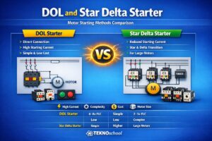
2. STAR-DELTA (Y-Δ) STARTER ⭐🔺
How it works:
Motor starts with windings connected in Star (Y) configuration
After motor reaches ~80% speed, contactors switch to Delta (Δ)
Star connection reduces voltage across each winding to 58% (1/√3)
The Numbers:
Starting current: Reduced to 33% of DOL (about 2-2.5x normal)
Starting torque: Also reduced to 33% of DOL
Switchover: 5-10 seconds typical
Cost: Low to moderate
Pros:
Drastically reduces starting current (kind to electrical supply)
Lower cost than electronic starters
No heat dissipation during running (unlike soft starters)
Well-proven, reliable technology
Cons:
Starting torque also cut to 33% (may not start heavy loads)
Current spike during star-to-delta changeover
Motor must have all six winding ends brought out (not all motors do)
May need timer adjustment for different loads
When to use Star-Delta:
Medium motors (11-150kW range)
Light starting loads: centrifugal pumps, fans, small compressors
Where supply cannot handle DOL current
Cost-sensitive applications
Important: Only works for loads that can start with 33% torque!
3. SOFT STARTER (ELECTRONIC REDUCED VOLTAGE) 📱
How it works:
Uses thyristors (electronic switches) to gradually ramp up voltage
Smooth, controlled acceleration
Can control both starting and stopping ramps
The Numbers:
Starting current: Adjustable limit (typically 2-4x normal)
Starting torque: Smooth ramp, fully adjustable
Start time: Adjustable (5-30 seconds typical)
Cost: Moderate
Pros:
Smooth acceleration protects mechanical components
Controlled current (no voltage dips)
Prevents water hammer in pump systems
Programmable start/stop profiles
Compact, no moving parts
Can do current limiting
Built-in motor protection features
Cons:
More expensive than star-delta
Generates heat during starting (needs cooling)
Creates harmonics (electrical noise)
No speed control during running (full speed only)
When to use Soft Starter:
Medium to large motors (15-500kW)
High-inertia loads needing smooth start
Pump systems (prevents water hammer)
Conveyor belts (prevents spillage during start)
Where mechanical shock must be minimized
Applications needing ramp-down (pump stop control)
4. VARIABLE FREQUENCY DRIVE (VFD) 🎛️
How it works:
Converts incoming AC power to DC, then back to variable-frequency AC
Controls both frequency and voltage simultaneously
Provides true speed control from zero to full speed and beyond
The Numbers:
Starting current: Very low (~1.5x normal)
Starting torque: Excellent (150-200% at low speeds)
Start time: Fully adjustable
Speed control: Continuous 0-120% (or more)
Cost: Highest
Pros:
Excellent starting performance—smooth and controlled
True speed control throughout operation
Massive energy savings on variable-torque loads (pumps, fans: 20-50% energy reduction)
Soft start/stop included
Process optimization through speed control
Built-in comprehensive motor protection
Can run multiple speed profiles
Cons:
Most expensive starting method
Generates harmonics (may need filters)
Can cause bearing currents in large motors (need insulated bearings)
Cable length limitations
More complex, requires programming/commissioning
Cooling/ventilation needs
When to use VFD:
Variable-torque loads (pumps, fans—huge energy savings!)
Process requiring speed variation during operation
Where energy efficiency is priority
Precision speed control applications
Modern installations prioritizing flexibility
Energy Savings Example:
Fan/pump at 50% speed = 12.5% power consumption
Running at 75% speed = 42% power
This is where VFDs pay for themselves quickly
5. ROTOR RESISTANCE STARTER (Slip Ring Motors Only) 🎚️
How it works:
External resistors connected to rotor windings through slip rings and brushes
Resistors progressively cut out (reduced) as motor speeds up
Can be manual (operator controlled) or automatic (contactor sequence)
The Numbers:
Starting current: Controlled, relatively low
Starting torque: Very high (2-2.5x rated)
Start time: Adjustable by controlling resistance cutout
Cost: Moderate to high (motor + resistance bank)
Pros:
Highest starting torque with low current
Smooth, controlled acceleration
Best for high-inertia, high-torque starts
Very robust for heavy-duty cycles
Cons:
Only works with slip ring motors
Brushes and slip rings need regular maintenance
External resistance bank (takes space, generates heat)
More complex than squirrel cage starters
When to use Rotor Resistance:
Heavy-duty applications: crushers, ball mills, hoists, cranes
Extreme high-inertia loads
High breakaway torque requirements (starting against load)
Mining and heavy industry
Where load cannot be decoupled during start
Quick Comparison Table 📊
| Starting Method | Starting Current | Starting Torque | Cost | Complexity | Best Application |
|---|---|---|---|---|---|
| DOL 🔌 | ⚡⚡⚡⚡⚡ (500-800%) | 💪💪💪💪💪 (150-250%) | 💰 | ⭐ Simple | Small motors, strong supply |
| Star-Delta ⭐ | ⚡⚡ (170-270%) | 💪💪 (50-80%) | 💰💰 | ⭐⭐ Moderate | Light loads, medium motors |
| Soft Starter 📱 | ⚡⚡ (200-400%) | 💪💪💪 Adjustable | 💰💰💰 | ⭐⭐ Moderate | Smooth start needed |
| VFD 🎛️ | ⚡ (150%) | 💪💪💪💪 (150-200%) | 💰💰💰💰 | ⭐⭐⭐⭐ Complex | Variable speed, energy saving |
| Rotor Resistance 🎚️ | ⚡⚡ Controlled | 💪💪💪💪💪 (200-250%) | 💰💰💰 | ⭐⭐⭐ Complex | Heavy-duty, high torque |
🎯 APPLICATIONS BY EQUIPMENT TYPE
💧 PUMPS
Centrifugal Pumps (Most Common):
Load characteristic: Variable torque (torque increases with square of speed)
Starting: Easy—low breakaway torque
Typical power: 1kW to several MW
Starting method:
Small (<15kW): DOL
Medium (15-75kW): Star-delta
Large: Soft starter or VFD
VFD benefit: At 50% speed, power drops to 12.5%—massive energy savings for variable flow
Special notes: Soft starter prevents water hammer (pressure surges in pipes)
Positive Displacement Pumps (Gear, Screw, Piston):
Load characteristic: Constant torque
Starting: Moderate to hard (against system pressure)
Starting method: Soft starter or VFD preferred
Special notes: May need relief valve during start
🗜️ COMPRESSORS
Centrifugal Compressors:
Load characteristic: Variable torque
Starting: Usually unloaded start (blow-off valve open)
Typical power: 75kW to several MW
Starting method: Star-delta, soft starter, or VFD (large units)
Special notes: Surge control critical during operation
Reciprocating Compressors:
Load characteristic: Constant torque, pulsating
Starting: High torque, often must start loaded
Starting method: Soft starter for medium, slip ring with rotor resistance for large
Special notes: High starting torque design motor required
Screw Compressors:
Load characteristic: Constant torque
Starting: Moderate, often includes unloading mechanism
Starting method: Star-delta or VFD
VFD benefit: Excellent for variable air demand, energy savings
🌬️ FANS & BLOWERS
Centrifugal Fans (Most Common):
Load characteristic: Variable torque (torque ∝ speed²)
Starting: Very easy—lowest starting torque of any load
Typical power: 0.5kW to 1MW+
Starting method:
Small: DOL
Medium: Star-delta (works perfectly)
Variable speed: VFD (huge energy savings)
VFD benefit: Best return on investment for fans—can save 30-60% energy
Applications: HVAC, ventilation, industrial process air, boiler induced/forced draft fans
Axial Fans:
Similar to centrifugal but even easier to start
Perfect candidate for simple DOL starting
🏗️ CONVEYORS
Belt Conveyors:
Load characteristic: Constant torque
Starting: Gentle start critical to prevent:
Belt stress/damage
Material spillage
Mechanical shock to structure
Typical power: 5-500kW
Starting method: Soft starter highly recommended (smooth ramp)
Special notes: Long conveyors may need multiple motors with synchronized soft starters
Chain Conveyors:
Similar requirements to belt conveyors
Soft start prevents chain shock loads
🔨 CRUSHERS & MILLS
Jaw/Cone Crushers:
Load characteristic: High inertia, variable load, may start under load
Starting: Very difficult—highest torque requirement
Typical power: 100kW to several MW
Starting method: Traditionally slip ring with rotor resistance; modern: large VFD
Special notes: Must handle jamming and reverse jogging
Ball Mills (Grinding Mills):
Load characteristic: Extremely high inertia (rotating drum filled with steel balls and material)
Starting: Highest starting torque of any common application
Starting method: Slip ring with liquid resistance or multi-megawatt VFD
Special notes: Can take several minutes to reach full speed
🏗️ CRANES & HOISTS
Overhead Cranes, Gantry Cranes:
Load characteristic: Intermittent duty (frequent starts/stops), variable load
Duty cycle: S3, S4, S5 (not continuous)
Starting: Frequent, precise control needed
Traditional method: Slip ring motor with rotor resistance (stepless control)
Modern method: VFD with squirrel cage (better control, less maintenance)
Special features: Dynamic braking, slow speed (inching) capability
Typical power: 5-200kW per motion
Other Common Applications 🏭
| Equipment | Load Type | Starting Challenge | Typical Starter | Power Range |
|---|---|---|---|---|
| Mixers/Agitators 🌀 | Constant or variable | Viscous loads | Soft starter | 5-200kW |
| Machine Tools 🔧 | Variable | Quick response | VFD | 1-50kW |
| Extruders 📦 | Constant | High torque | VFD or slip ring | 50-500kW |
| Saws ⚙️ | Variable | Quick start | DOL or soft starter | 1-30kW |
| Textile Machinery 🧵 | Constant | Synchronized speed | VFD | 1-100kW |
| Escalators/Elevators 🛗 | Variable | Smooth, safe | VFD | 10-100kW |
| Wood Chippers 🌳 | High inertia | Hard start, jamming | Soft starter or slip ring | 50-300kW |
🏭 MAJOR MANUFACTURERS & MODEL SERIES
Global Leaders 🌍
ABB (Switzerland/Sweden)
M3BP Series: Process performance motors, 0.75-315kW, IE2/IE3 efficiency
M2BAX Series: General purpose aluminum frame
Known for reliability and efficiency
Wide voltage range options
SIEMENS (Germany)
SIMOTICS GP: General purpose line, 0.09-450kW
SIMOTICS SD: Severe duty applications
Excellent integration with Siemens automation
Premium quality, higher price point
WEG (Brazil)
W22 Series: 0.12-500HP, IE3/IE4 efficiency
Known for excellent value for money
Strong in energy-efficient designs
IP55 standard enclosure
Growing global presence
NIDEC (Japan)
High-efficiency motors
Known for precision and quality
Strong in industrial automation
SCHNEIDER ELECTRIC (France)
Energy-efficient motor ranges
Good integration with their control systems
Wide distribution network
TECO-WESTINGHOUSE (Taiwan/USA)
Broad industrial motor range
Good availability
Competitive pricing
BALDOR (now ABB)
Strong in North American market
Heavy-duty industrial focus
Indian Manufacturers 🇮🇳
KIRLOSKAR ELECTRIC
Wide range LV and HV motors
Strong Indian presence
Good after-sales support locally
Competitive pricing
ABB INDIA
Local manufacturing of global designs
Full range availability
Premium segment
BHARAT BIJLEE
Established player in heavy-duty motors
Strong in HV motors
Mumbai-based, national presence
CROMPTON GREAVES (CG)
Comprehensive industrial motor range
Good distribution network
Value segment to premium
HAVELLS
Light to medium duty motors
Strong in domestic and light industrial
Widely available
SIEMENS INDIA
Local assembly of SIMOTICS range
Premium segment
Excellent technical support
Typical Model Number Breakdown
Example: M3BP 250SMA 2
M3BP = Series designation
250 = Frame size
S/M/L = Shaft length (Short/Medium/Long)
MA/MB = Frame variant
2 = Number of poles
Example: 1LA70604AB10
1LA = Series (Siemens SIMOTICS GP)
7 = Frame size group
06 = Specific frame
04 = Pole number
AB10 = Variant code
📏 MOTOR SELECTION QUICK GUIDE
By Power & Voltage
| Application Power | Typical Voltage | Preferred Type | Starting Method | Cooling |
|---|---|---|---|---|
| 0.37-7.5kW | 400V | Squirrel cage | DOL | IP55 TEFC |
| 7.5-30kW | 400V | Squirrel cage | Star-delta | IP55 TEFC |
| 30-200kW | 400V/690V | Squirrel cage | soft starter or VFD | IP55 TEFC |
| 200kW-1MW | 690V/3.3kV | Squirrel cage | VFD | IC411 or IC611 |
| 1-5MW | 3.3kV/6.6kV | Squirrel cage or slip ring | VFD or rotor resistance | IC611 or IC81W |
| Above 5MW | 11kV | Slip ring | Rotor resistance or mega-VFD | IC81W |
By Application Type
| Load Characteristic | Equipment Examples | Motor Type | Starting Method |
|---|---|---|---|
| Variable Torque (Torque ∝ Speed²) | Centrifugal pumps, fans, blowers | Squirrel cage | DOL/Star-delta/VFD (VFD for energy savings) |
| Constant Torque | PD pumps, conveyors, extruders | Squirrel cage | Soft starter or VFD |
| High Starting Torque | Crushers, mills, loaded starts | Slip ring or VFD | Rotor resistance or VFD |
| High Inertia | Large fans, ball mills | Slip ring or VFD | Rotor resistance or extended start |
| Intermittent Duty | Cranes, hoists, elevators | Slip ring or squirrel | VFD for modern installations |
| Precision Speed Control | Machine tools, textile, extruders | Squirrel cage + VFD | VFD |
✅ FINAL TIPS FOR SUCCESS
Selecting a Motor:
Know your load: power requirement, starting torque, duty cycle
Know your supply: voltage, frequency, available fault current
Know your environment: indoor/outdoor, clean/dirty, hazardous classification
Choose appropriate IP rating for environment
Consider energy efficiency—IE3 is current standard, IE4 for critical applications
Size starter/protection appropriately
Installation:
Perfect alignment is critical—don’t rush this step
Proper grounding saves lives and equipment
Ensure adequate cooling airflow
Use correct cable sizes
Verify rotation direction before coupling
Maintenance:
Regular bearing lubrication (follow manufacturer schedule)
Keep motor clean and cooling paths clear
Monitor vibration and temperature
Check terminal tightness annually
Test insulation resistance periodically
Keep records
Troubleshooting Basics:
Motor won’t start → Check supply, connections, rotation lock
Trips on overload → Check load, voltage, current balance
Runs hot → Check ventilation, load, voltage
Noisy → Check bearings, alignment, mounting
Vibration → Check balance, alignment, bearing condition
🎉 THE THREE-PHASE INDUCTION MOTOR—SIMPLE, ROBUST, RELIABLE! 🎉
Over a century of proven technology, still going strong in Industry 4.0 ⚙️🌍