Temperature Transmitters: Design, Functionality & Industrial Applications
Complete Guide to Industrial Temperature Transmitters
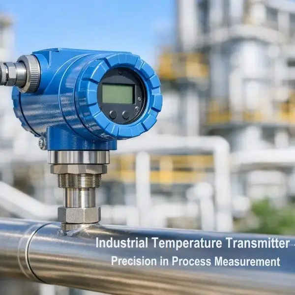
Temperature transmitters are critical instrumentation devices that convert temperature sensor signals into standardized output signals for industrial control systems. They serve as the interface between temperature sensors (RTDs, thermocouples) and control systems, enabling precise temperature monitoring and control across manufacturing processes.
Introduction to Temperature Transmitters
A temperature transmitter accepts input from temperature sensors and converts the raw signal into a standardized output that can be transmitted over long distances without signal degradation. The transmitter compensates for sensor non-linearities, provides signal amplification, and enables isolation between the field device and control system.
Modern temperature transmitters have evolved from simple analog signal converters to sophisticated digital devices with diagnostic capabilities, configuration flexibility, and multi-protocol communication options. They are essential in chemical plants, refineries, power generation facilities, and pharmaceutical manufacturing where accurate temperature measurement directly impacts product quality, safety, and process efficiency.
Major Manufacturers and Popular Models
Emerson (Rosemount)
· Rosemount 3144P: HART-enabled with sensor backup functionality
· Rosemount 644: Universal temperature transmitter with dual input capability
· Rosemount 648: Wireless temperature transmitter for remote applications
Endress+Hauser
· iTEMP TMT162: Compact transmitter with universal input
· iTEMP TMT181: Profibus PA model with advanced diagnostics
· iTEMP TMT85: Foundation Fieldbus variant
Yokogawa
· YTA110: Universal input with HART protocol
· YTA320: Foundation Fieldbus temperature transmitter
· YTA610: Profibus PA model with multi-sensor capability
Siemens
· SITRANS TH300: Programmable head-mounted transmitter
· SITRANS TH400: Rail-mounted with HART/Profibus compatibility
· SITRANS TF280: Foundation Fieldbus temperature transmitter
ABB
· TTF300: Foundation Fieldbus transmitter
· TTP100: Profibus PA model
· TSP300: Smart temperature transmitter with multi-protocol support
Honeywell
· STT3000: Smart temperature transmitter with universal input
· STT800: Wireless temperature solution
· STT170: Economic HART-enabled model
Construction and Design
Temperature transmitters typically consist of a rugged housing designed for industrial environments with IP65-IP68 ingress protection ratings. The housing contains electronics boards, terminal blocks, and configuration interface ports.
Physical Components
The transmitter housing is manufactured from die-cast aluminum, stainless steel, or engineering plastics depending on the application environment. A removable cover provides access to configuration switches, LCD displays, and terminal connections. Environmental seals protect internal electronics from moisture, dust, and corrosive atmospheres.
Head-mounted transmitters install directly onto temperature sensor connection heads, minimizing wiring and reducing installation costs. Rail-mounted variants install in control panels or junction boxes, allowing centralized installation of multiple transmitters.
Terminal Configuration
Input terminals accept RTD or thermocouple connections with compensation for lead resistance. Output terminals provide current loop connections with separate power supply terminals. Advanced models include auxiliary terminals for sensor backup, relay outputs, or secondary measurement inputs.
Internal Electronics Architecture
The core electronics consist of input conditioning circuitry, microprocessor-based signal processing, and output driver circuits.
Input Stage
The input stage provides high-impedance buffering for thermocouple signals or precision current sources for RTD excitation. Cold junction compensation circuitry automatically corrects thermocouple measurements. Programmable gain amplifiers scale the sensor signal to appropriate levels for analog-to-digital conversion.
Signal Processing
A microcontroller manages sensor linearization using stored polynomial equations or lookup tables. The processor applies user-configured parameters including sensor type, range, damping, and engineering units. Self-diagnostics continuously monitor sensor health, detecting open circuits, short circuits, and out-of-range conditions.
Output Stage
Digital-to-analog converters generate the 4-20 mA output signal with current limiting and short-circuit protection. Digital communication circuits modulate HART signals onto the analog loop or manage fieldbus protocol communications. Isolation barriers protect control system inputs from ground loops and voltage transients.
Working Principle
Temperature transmitters operate by converting the sensor’s electrical characteristics into proportional current or digital signals.
RTD Measurement
The transmitter supplies a precision constant current through the RTD sensor. As temperature changes, the RTD resistance varies predictably. The transmitter measures the resulting voltage drop, linearizes the response curve, and converts the temperature value to the configured output range.
For a Pt100 RTD with 0-100°C range mapped to 4-20 mA output, the transmitter calculates the temperature from measured resistance, applies the Callendar-Van Dusen equation for linearization, and scales the result such that 0°C produces 4 mA and 100°C produces 20 mA.
Thermocouple Measurement
Thermocouple transmitters measure the millivolt signal generated by the thermocouple junction while simultaneously measuring the terminal block temperature for cold junction compensation. The microprocessor applies the appropriate thermocouple polynomial equation and adds the cold junction correction to determine the actual process temperature.
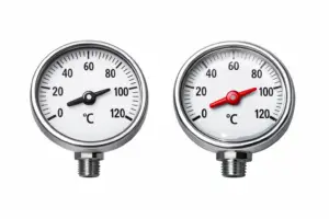
Analog Temperature Transmitters
Analog transmitters provide a simple 4-20 mA current output proportional to the measured temperature. The 4 mA signal represents the lower range value while 20 mA represents the upper range value, creating a linear relationship between temperature and current.
This current signal travels over two-wire loops where the same wires carry both power and signal. The 4-20 mA standard offers inherent noise immunity since current remains constant regardless of wire resistance. A 4 mA live zero allows the receiving system to distinguish between a low reading and a broken wire condition.
Configuration requires physical adjustments using potentiometers or DIP switches to set sensor type, range, and damping parameters. These transmitters excel in simple applications requiring reliable measurement without communication overhead.
Digital Temperature Transmitters
Digital transmitters incorporate microprocessor-based electronics enabling advanced functionality beyond basic signal conversion. They support remote configuration, self-diagnostics, and multi-variable measurement capabilities.
Enhanced Features
Digital models store multiple sensor configurations allowing quick changeover between measurement ranges or sensor types. Built-in diagnostics detect sensor drift, connection problems, and electronic failures before they cause process upsets. Totalizer functions track temperature-time integrals useful for batch processes.
Configuration Interface
Local configuration occurs through magnetic programming tools that communicate through the transmitter housing without opening the cover, maintaining area classification integrity. Display modules show process values, diagnostic messages, and configuration parameters in real-time.
HART Protocol Transmitters
HART (Highway Addressable Remote Transducer) technology superimposes digital communication signals onto the 4-20 mA analog loop using frequency shift keying. The digital signal does not interfere with the analog measurement, providing backward compatibility with existing analog systems.
Functionality
HART transmitters enable bi-directional communication for configuration, calibration, and diagnostics while maintaining the analog signal for primary control. A handheld communicator or PC-based software connects to the loop for accessing transmitter parameters without interrupting the process measurement.
Process variable, sensor temperature, diagnostic status, and configuration parameters transmit digitally. Users can remotely adjust range settings, apply damping filters, enable sensor backup features, and retrieve calibration history. Multiple transmitters on the same loop support multi-drop mode where each device has a unique address and outputs 4 mA while communicating digitally.
Foundation Fieldbus Transmitters
Foundation Fieldbus is a fully digital, bi-directional communication protocol designed specifically for process automation. Temperature transmitters on Fieldbus networks act as intelligent devices capable of executing control logic and sharing multiple process variables.
Advanced Capabilities
These transmitters publish primary variable, sensor status, and diagnostic information simultaneously. Function blocks within the transmitter perform PID control, signal characterization, and alarm management, distributing control intelligence to the field level.
The bus powers multiple devices over the same two-wire network while maintaining communication speeds up to 31.25 kbps. Segment topology supports up to 32 devices per segment with intrinsically safe installations in hazardous areas. Device Description (DD) files and Electronic Device Description Language (EDDL) provide standardized integration with any host system supporting Foundation Fieldbus.
Profibus Transmitters
Profibus PA (Process Automation) is a fieldbus protocol optimized for process instrumentation with intrinsic safety and bus-powered operation. Temperature transmitters communicate using the Profibus DP protocol adapted for process applications.
Protocol Features
Profibus PA transmitters transmit measured temperature, sensor diagnostics, and device status information at configurable update rates. The protocol supports cyclic data exchange for real-time process values and acyclic communication for configuration and diagnostics.
Bus topology allows up to 126 devices per segment with communication speeds of 31.25 kbps on the PA segment. Segment couplers link PA segments to high-speed DP networks operating at up to 12 Mbps. GSD (General Station Description) files define device capabilities for host system integration.
IoT-Enabled Temperature Transmitters
IoT temperature transmitters incorporate wireless communication technologies including Wireless. HART, ISA100.11a, LoRaWAN, and cellular connectivity. These devices enable remote monitoring, cloud-based analytics, and integration with Industrial Internet of Things platforms.
Connectivity Options
Wireless transmitters eliminate wiring costs in retrofit applications or locations where cable installation is impractical. Battery-powered models operate for years on single power cells, transmitting periodic updates to gateway devices that relay data to cloud platforms or on-premise historians.
Edge computing capabilities process data locally, reducing bandwidth requirements by transmitting only summary statistics, alarm conditions, or trends rather than continuous raw data. OPC-UA servers within the transmitter enable direct connection to enterprise systems without proprietary middleware.
Cloud integration allows viewing temperature data through web dashboards, mobile applications, and integration with analytics platforms for predictive maintenance and process optimization. API access enables custom application development and integration with third-party systems.
DCS and PLC Integration
Analog Transmitter Connections
Analog temperature transmitters connect to DCS and PLC analog input cards through two-wire or four-wire configurations. Two-wire transmitters draw power from the loop while generating the 4-20 mA signal on the same wires. Four-wire transmitters use separate wires for power supply and signal output.
The DCS or PLC analog input card supplies 24 VDC power through a precision resistor (typically 250 ohms). The transmitter’s 4-20 mA current flows through this resistor, creating a 1-5 VDC voltage drop that the input card measures and converts to a digital value. The controller scales this value to engineering units based on configured range parameters.
Wiring requires shielded twisted pair cables with the shield grounded at one end only to prevent ground loops. For critical measurements, redundant transmitters connect to separate input cards providing automatic failover capability.
Digital Transmitter Connections
HART transmitters connect identically to analog transmitters for the primary 4-20 mA signal. The DCS or PLC requires a HART modem or multiplexer for accessing digital data. This device connects in parallel with the analog input, allowing simultaneous analog measurement and digital communication.
Foundation Fieldbus transmitters connect to fieldbus interface cards in the DCS or PLC. These cards provide power, manage communication, and execute the bus schedule. Multiple transmitters connect in parallel on the same segment using fieldbus-approved cables with specified capacitance and inductance characteristics.
Profibus transmitters require Profibus interface cards or communication processors in the PLC or DCS. The segment terminates with active terminators at both ends maintaining signal integrity. Repeaters extend segment length beyond standard limitations when necessary.
Installation in Hazardous Areas
Hazardous area installations require temperature transmitters with appropriate certifications for the specific zone classification. The installation method depends on the protection concept employed.
Intrinsic Safety
Intrinsically safe transmitters limit energy levels to prevent ignition of flammable atmospheres. These devices install with certified intrinsic safety barriers or isolators that restrict voltage and current to safe levels even under fault conditions.
Blue cable identifies intrinsically safe circuits, and strict segregation maintains separation from non-IS circuits. Earthing requirements follow manufacturer specifications, typically connecting the barrier ground to a dedicated ground bus with low impedance to the plant ground grid.
Entity parameters (Ui, Ii, Pi, Ci, Li) ensure the combination of transmitter, cable, and barrier maintains safe energy levels. Cable capacitance and inductance must not exceed maximum values specified by the barrier manufacturer.
Explosion-Proof Housings
Explosion-proof (flameproof) transmitters contain any internal explosions within the rugged housing, preventing flame propagation to the external atmosphere. The housing withstands internal explosion pressures and cools escaping gases below ignition temperature.
Conduit seals within 18 inches of the housing prevent gas migration through the conduit system. Thread engagement requirements ensure proper flame path maintenance. Regular inspection verifies housing integrity and thread condition.
Increased Safety
Increased safety transmitters incorporate design features preventing excessive temperatures and electrical arcing under normal operation. These devices cannot be opened while energized, and special tools access terminals to prevent unauthorized modification.
Installation in Flammable Areas
Flammable area installations follow similar principles to hazardous areas but address specific risks associated with flammable liquids, dusts, or fibers.
Zone Classification
Temperature transmitters installed in Class I Division 1 or Zone 0 locations require intrinsically safe or explosion-proof protection. Division 2 or Zone 1 locations may permit general purpose equipment in sealed enclosures if approved for the application.
Proper area classification studies identify the extent of hazardous zones around process equipment. Temperature measurement points near flammable liquid storage, transfer points, or process vessels require appropriate protection levels based on release frequency and ventilation.
Installation Best Practices
Mount transmitters outside the hazardous zone when possible, using thermowells to position sensors in the process while keeping electronics in safe areas. When field mounting is necessary, select the highest protection level practical for the application.
Cable gland selection ensures appropriate sealing and maintains area classification integrity. Certified glands prevent gas ingress through cable entries. Regular maintenance verifies seal integrity and housing condition.
Document all installations including cable types, barrier settings, and entity calculations for inspection and audit purposes. Maintain hot work permits and gas-free certificates during maintenance activities.