LV Capacitor Banks and Control Panels
Understanding LV Capacitor Banks and Control Panels: Construction, Features & Best Practices
Improving power factor is one of the most effective ways to enhance electrical system efficiency, reduce energy losses, and optimize overall plant performance. At the heart of this improvement lies the Low Voltage (LV) Capacitor Bank and its associated Control Panel, both engineered to deliver reliable reactive power compensation in industrial and commercial installations. This article explores their purpose, construction, essential components, and the standards that guide their design.
Why LV Capacitor Banks Matter
In any electrical system, inductive loads such as motors, transformers, and welding machines draw reactive power. This reduces the power factor, leading to higher current flow, increased losses, and penalties from utility companies. LV capacitor banks supply the required reactive power locally, improving the power factor and stabilizing the system.
A well‑designed capacitor bank ensures:
- Reduced demand charges
- Improved voltage profile
- Lower transformer and cable loading
- Enhanced system efficiency
Design Standards and Compliance
Capacitor banks and their control panels must comply with relevant electrical standards to ensure safety, reliability, and long‑term performance. These standards define requirements for construction, protection, testing, and installation.
Some of the key areas covered by these standards include:
- Shunt capacitor design
- Protection levels for enclosures
- Factory‑built switchgear assemblies
- Air‑break switches and fuse combinations
- AC contactor performance
Adhering to these guidelines ensures that the equipment performs consistently under varying load and environmental conditions.
Constructional Features of LV Capacitor Banks
A capacitor bank is more than a set of capacitors; it is a complete engineered assembly designed for durability and safe operation. Key constructional features include:
1. System Compatibility
Capacitor banks are designed for 415 V, 3‑phase, 4‑wire, 50 Hz systems with solid earthing. This ensures seamless integration into standard industrial power networks.
2. Robust Mechanical Structure
A typical bank includes:
- Hermetically sealed capacitor units
- Supporting post insulators
- Sheet‑steel cubicles
- Bus bars and connecting strips
- Foundation channels
- Corrosion‑resistant rating plates
These components ensure mechanical stability and long service life.
3. Modular Capacitor Units
Capacitor banks often use multiple single‑phase, self‑cooled units arranged in series or parallel to achieve the required kVAR rating. This modularity ensures that the failure of one unit does not compromise the entire bank.
4. Discharge Safety
Each capacitor unit is equipped with a continuously rated discharge device that reduces residual voltage to below 50 V within one minute, ensuring safe maintenance and handling.
5. Overload Capability
Capacitors are designed to withstand:
- Up to 10% over‑voltage
- Up to 15% over‑current
- Up to 30% excess reactive output
This ensures resilience during fluctuating load conditions.
6. Individual Protection
Each capacitor unit is protected by HRC fuses with visual indicators, enabling quick identification of faults.
7. High‑Quality Dielectric
Modern capacitor units use metallic polypropylene dielectric with aluminum foil, offering low losses and high reliability.
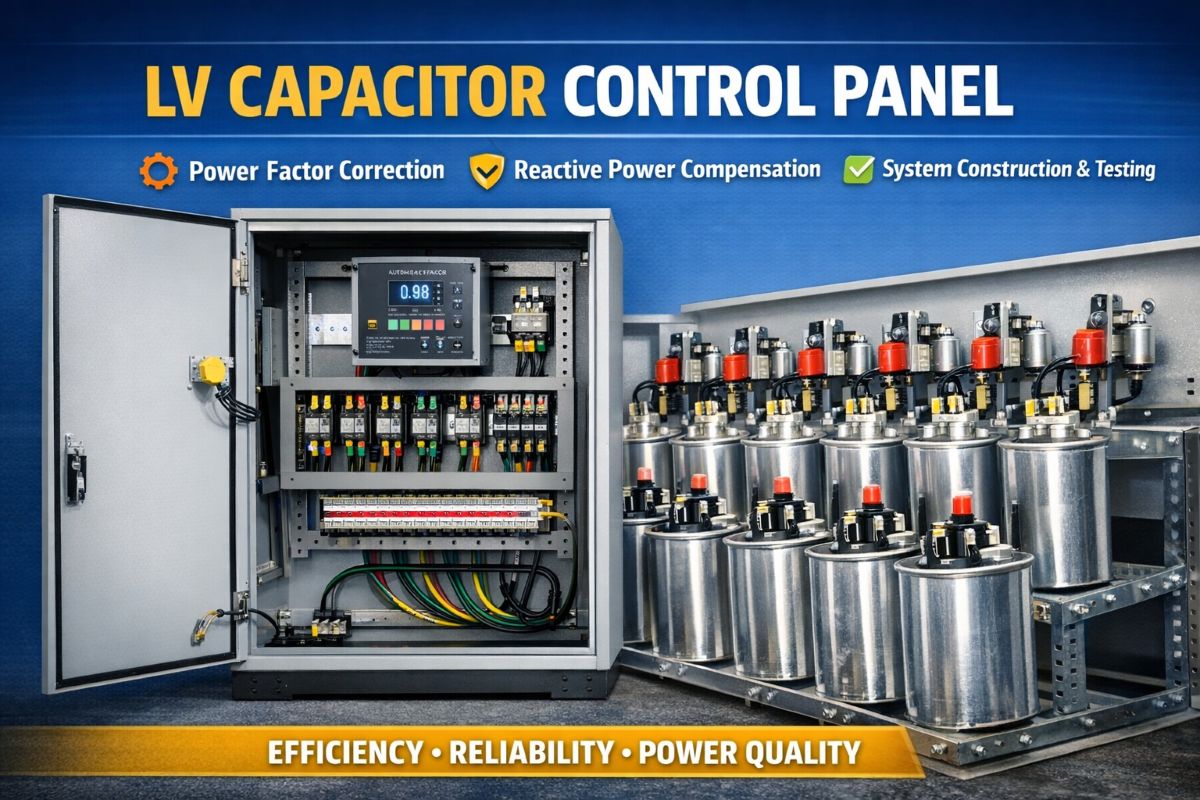
Inside the Capacitor Control Panel
The control panel is the brain of the capacitor bank, managing switching operations and ensuring optimal power factor correction.
1. Rugged Construction
The panel is typically:
- Indoor type
- Floor‑mounted
- Dust‑ and vermin‑proof
- Built with 2 mm CRCA steel for the frame and 1.6 mm steel for doors
Neoprene gaskets ensure proper sealing against environmental contaminants.
2. Essential Components
A well‑designed control panel includes:
- Removable gland plates
- Double‑compression cable glands
- 650 V grade terminal blocks
- Earth bus bar
- PVC‑insulated copper wiring with ferrules
- Aluminum or copper bus bars with color coding
These components ensure safe and organized wiring.
3. APFC Relay
The Automatic Power Factor Control (APFC) relay is the heart of the system. It provides:
- Auto/manual selection
- Cyclic switching
- Power factor sensitivity
- Under‑voltage and over‑voltage protection
- Integrated PF meter
The relay receives input from a 5 A CT mounted on the main bus bar, enabling accurate monitoring.
4. Panel Finish
The panel undergoes a multi‑stage surface treatment process, including:
- Cleaning
- Acid pickling
- Phosphating
- Oven drying
It is then coated with zinc‑chromate primer and finished with two coats of synthetic enamel paint.
Testing, Inspection & Documentation
Before commissioning, capacitor banks and control panels undergo:
- Routine tests as per standards
- Submission of type test reports
- Visual inspection and witness testing
Manufacturers also provide:
- General arrangement drawings
- Wiring diagrams
- Sequential switching schematics
- Installation and maintenance manuals
This documentation ensures smooth installation, operation, and long‑term maintenance.
Conclusion
LV capacitor banks and their control panels play a crucial role in maintaining power quality and improving system efficiency. Their design combines electrical engineering precision with robust mechanical construction, ensuring reliable performance even under demanding industrial conditions. By understanding their components, features, and compliance requirements, industries can make informed decisions that lead to better energy management and reduced operational costs.